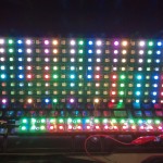
The intelligent Matrix and RowGB

Anool, Kevin, and I have been working on a cool new project based on 5050-2811 RGB pixels.  We just got the first boards back and they are amazing.

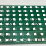
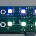
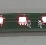
  • RowGB has 16 individualally addressable 24-bit RGB LEDs and can be chained together either horizontally or vertically to make a 2D array.
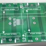
  • TiM (the intellegent matrix) is an array of 8×16 individually addressable pixels of the same ilk as RowGB.  It is essentially 8 pre-stacked RowGBs but with a very flexible control circuit that allows you to control the whole array with a single pin or up to 10 boards (1280 pixels) chained together using 8 input pins.

Now that the tests are complete, we are ready to go into production.  Please send us an email at info@wyolum.com you’d like to be updated on availability.


Re-Paper Experiments

I was lucky enough to get a preview of repaper.org‘s new Electronic Paper Display (also available here) with a breakout board.  It is pretty cool that e-paper has finally made its way to makers with a few other products coming out too, like the E-ink shield from Seeed Studio.

In case you don’t know, e-ink technology is enables a low-power display that can maintain its image without power indefinitely.  My Dad described it well as “like an electronic etch-a-sketch?”  If your project needs a fast refresh rate, e-ink will not do what you want.  The setup below refreshes once every couple of seconds.

The hardware is specifically designed for the TI 430 Launchpad project board, but it turned out to be easy enough wire it up to our own AlaMode with the pin assignment table provided.  It even worked the first try (a rare event for me).

The open source software works with Launchpad and Arduino.  It is in its early stages so programming is a bit of a challenge at this point.  The example code includes a demo for displaying images from EEPROM (external chip) or PROGMEM (limted space).  But I think SD really seems like the way to go here and AlaMode already has an SD slot on board so I wanted to see if I could get them working together.  It turned out to be more of a challenge than I was expecting (story of my life).

Displaying on an E-ink requires four steps: two to erase the old image and two two draw the new image. The extra steps are designed to avoid and eliminate image ghosting. A ghost image is the remnants of an old image after a new image is displayed.  This might be made easier in the future with a nice library that hides all of the details.  In the mean time, I just wanted to get the details out there.

I started poking around the header file EPD.h and found a generic reader template which turned out to be the key.  The comment is my own.

/*
* A generic reader template
*
* buffer -- write buffer for outgoing bytes
* address -- byte index, 0 to display height
* length -- number of bytes to read
*/
typedef void EPD_reader(void *buffer, uint32_t address, uint16_t length);

I wrote a function new_SD_reader() which complied with the EPD_reader template.

/*
 * SD card reader Comply with EPD_reader template
 *
 * buffer -- write buffer for outgoing bytes
 * address -- byte index, 0 to display height
 * length -- number of bytes to read
 */
void new_SD_reader(void *buffer, uint32_t address, uint16_t length){
  byte *my_buffer = (byte *)buffer;
  for(int i=0; i < length; i++){
    newFile.seek(address + i + 4);
    *(my_buffer + i) = newFile.read();
  }
}

The variable newFile is a File object opened elsewhere.  What would be handy here is an extra argument in the EPD_reader template to specify a filename.  Maybe in the next release.  As it is, I just made two similar functions for reading the new and old images.

Now can swap newFile and oldFile around in loop to change the image.

File newFile, oldFile;
char *datfilenames[2] = {"IMAGES/VENUS2.dat", "IMAGES/CAT2.dat"};
void next_image(char* fn){
  oldFile.close();
  oldFile = newFile;
  newFile = SD.open(fn);
  if(!newFile){
    Serial.println("new image not found");
    while(1){
      delay(1000);
    }
  }
}

// main loop
unsigned long int loop_count = 0;
void loop(){
...
	case 6:        // swap old image for new image
	  EPD.frame_cb_repeat(0, old_SD_reader, EPD_compensate);
	  EPD.frame_cb_repeat(0, old_SD_reader, EPD_white);
	  EPD.frame_cb_repeat(0, new_SD_reader, EPD_inverse);
	  EPD.frame_cb_repeat(0, new_SD_reader, EPD_normal);
	  // swap files
	  next_image(datfilenames[loop_count++ % 2]);
		state = 6;  // backe to picture nex time
		break;
...

The complete code can be found here.  Before you can run it, you will need to covert the xbm format to a simple byte format.  I’ve written this quick and dirty python code to do the trick.

Numpy/Scipy/Matplotlib on Raspberry Pi

Notice:  The method posted here worked great and was faster.  Try this first: http://www.cl.cam.ac.uk/projects/raspberrypi/tutorials/robot/downloads/

If that does not work then try this:

Ok, so this is the second time I had to stumble through this. Here the commands I used to finally get it to work. Total compile time was a few hours. The third and forth steps, contributed by Ty Rudder, are for an optional performance boost.

$ sudo apt-get install libblas-dev        ## 1-2 minutes
$ sudo apt-get install liblapack-dev      ## 1-2 minutes
[$ sudo apt-get install python-dev        ## Optional]
[$ sudo apt-get install libatlas-base-dev ## Optional speed up execution]
$ sudo apt-get install gfortran           ## 2-3 minutes
$ sudo apt-get install python-setuptools  ## ?
$ sudo easy_install scipy                 ## 2-3 hours
$ ## previous might also work: python-scipy without all dependencancies
$ sudo apt-get install python-matplotlib  ## 1 hour

… and the result is being able to do some nice processing on this blood pressure data. Below is 200 Hz pressure data, bandpass filtered between .5 and 5 Hz. You can clearly see the arterial pulses.

While I am jotting down hints, here is how to forward your X11 windows as root though ssh.

  1. From remote $ ssh -X pi@192.168.1.3 # change to pi’s IP address
  2. On Raspberry Pi $ sudo cp /home/pi/.Xauthority /root
  3. Now run your graphical program.  Window should display on remote computer.

Install Node (install webide or from source…):

  1. Download tarball from nodejs.org
  2. ./configure
  3. make
  4. make install 

Install simplejson (easy_install simplejson)

Install PIL (sudo apt-get install python-imaging)

Install PySerial (sudo apt-get install python-serial)

when installing power switch without RTC– both scripts rely on /etc/rc.local  if hwclock is not found, then script exits and does not run switch.sh.  FIX: run switch.sh before hwclock

FIX SD CARD: use Ubuntu boot disk creator to format disk, then dd newest distro

Color/Light Sensing Breakout Board

Our friend and fellow open hardware advocate, Jayson Tautic of Tautic.com is offering a cool breakout board on Tindie that word clock makers might want to take a look at.  It is a break out board for the TCS34717 – Color Light-to-Digital Converter.

ClockTHREEjr has a light dependent resistor or LDR board to measure brightness.  The problem with all of the LED switching taking place on the board, the analog measurement gets screwed up.  This breakout board could be the answer.  Besides measuring RGB color intensities, it also give an overall brightness reading which could be use to dim the LEDs when the lights go out.

Laser water flow detect / auto shutoff

The bad news is that once again we are learning the hard way.  I burned out our laser tube when water flow stopped unexpectedly (power strip?).

The good news is that we are now back in action.  Here is how we did it in case there are any other slow learners out there.

We tapped into the auto shutoff circuit that shuts off power to the laser when the door is open.  First we found this calibrated flow meter from SparkFun, then discovered this beauty from AdaFruit for only $9.99.  We went with the AdaFruit, of course.

Carduino is a prototype of a project meant to be a automobile battery monitor that can shut off a peripheral when the battery voltage starts to drop.  It was a simple matter to re-purpose the Carduino for this application.

The simple sensor has three leads: ground, 5V, and data.  The data line toggles between low and high when water (or air) is flowing and is steady (high or low) when flow stops.  The flow meter sample code provided by AdaFruit, gave us a jump start on the development.  The protection circuit code is simple, if the delay between low and high toggles on the flow meter is longer than expected, shut off the solid state relay.

I had to channel my inner Anool to figure out how to wire the unit and could not have done it without a healthy portion of Bald Wisdom.  It took a day.  Here is the result.  If you remove the side panel it is much easier.

The fluid circuit was a challenge of fittings and space.  I put the flow meter outside of the laser, but needed a right angle adapter to save space inside the laser.  I had to cut a spacer to mount the assembly (see in photo).