WyoLum EReader Library

IMG_20130515_190044_194

If you have an E-Paper Display form Adafruit, this library will allow you to draw points, lines, circles, ellipses, ASCII text and Unicode text (thanks Roman Czyborra).  Oh, and display images (in the WyoLum Image Format).  Please consider this an alpha release and help us find the bugs.

Overview
Besides looking great in full sun, E-Paper requires very little power and can maintain an image for a very long time without any power at all.  It costs energy only to turn the “page”.  If low power is the reason you are considering E-Paper in your design, then you probably want to consider the power requirements of the whole system.  If you can get by with an ATMEGA328 (like what is in most Arduino’s) your power requirements are greatly relaxed when compared to the more capable processors out there.   My Arduino DUE running “blink.ino” uses 120 mA at 5V whereas my UNO uses six times less: only 20 mA.

The problem is that the ATMEGA328 does not have enough memory to display very much.  That is where the SD card comes in.   Even a small SD card by today’s standard has an unimaginable amount of space for an Arduino project.  We use the SD to store, pre-formatted images (WIF) of any size, font files, and as the frame buffer for the display.  The frame buffer allows you to configure the next image behind the scene and the update the display all at once.  This is because the underlying EPD library does not support partial updates.

IMG_20130516_062723_614

Build it.
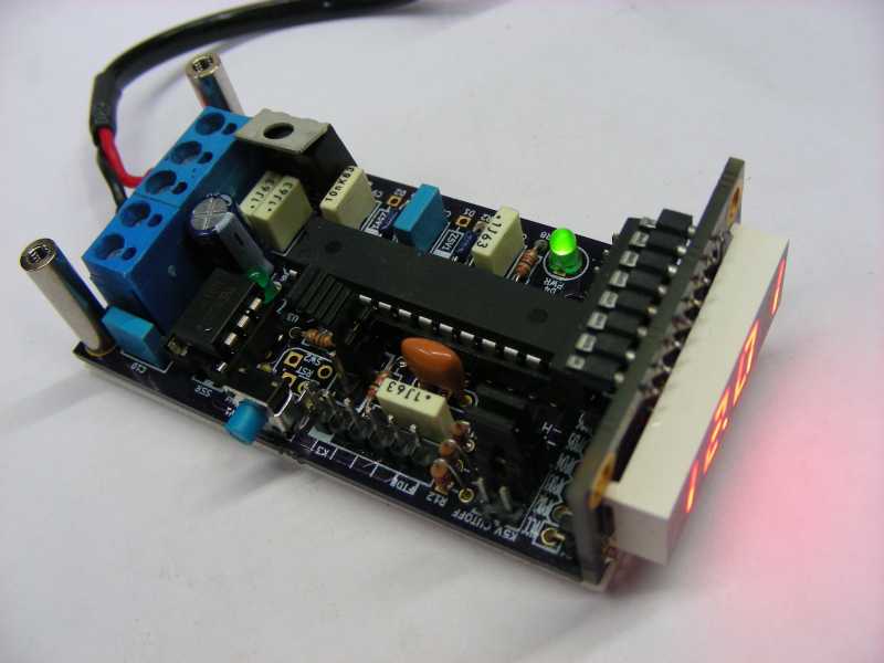
Note: We will be using the AlaMode for this tutorial, but any Arduino compatible with an SD card connected should work.

1. Use spare male header pins to connect the AlaMode to the EPD display using the wiring bundle included with the EPD or use gender bender jumpers as pictured here. You can find the pin assignments here on the repaper.org site.
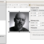
2. Create any images you’d like to be able to display using these instructions to WIF your images.
3. Store your images in the IMAGES/ directory on an SD card.

Software Installation.
Download the source code from GitHub and unzip it in a temporary location.  This will create a directory called “EPD-master”.  Move (or merge) the “libraries” directory to your “sketchbook location” which can be found in the “File->Preferences” dialog inside of the Arduino IDE.  I am using /home/justin/sketchbook.  The directory structure should look like this:Screenshot from 2013-05-16 07:22:37

[sketchbook]/
—AlaModeEPD/
—libraries/
——EReader/
———examples/
————EReader_demo/
————IMAGES/
————unifont.wff

Restart Arduino after setting up your directory structure.

AlaModeEPD — Displays all WIF files in the /IMAGES directory of the SD card.  This was the result of early experiments using the EPD.  It does not use the EPaper library.  You can safely ignore this sketch, but I left it as a reference.

EPaper_demo — This demonstrates some of the functionality in the EPaper library. It cycles through four screens displaying images, circles and text.  The AlaMode is compatible with the UNO board when run from a laptop.  Select “AlaMode” from the boards menu if you are programming from the Raspberry PI.

Screenshot from 2013-05-16 07:40:16

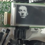
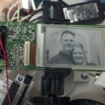
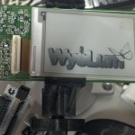
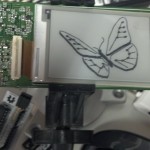
Copy the IMAGES/ directory to the root folder of your SD card.  Copy the file called “unifont.wff” to the root directory of your SD card.  Upload the program. The careful observer will notice that the “WyoLum ROCKS!!!” is at a new location each time the puzzle piece image comes up.  This highlights the fact that the display contents are dynamic.

Code walk through

Imports. All the libraries you need either come standard with Arduino, or are infcluded in the zip file download.

#include <inttypes.h>
#include <ctype.h>
#include <SPI.h>
#include <SD.h>
#include "EPD.h"
#include "S5813A.h"
#include "EReader.h"

A global variable to store unicode data

uint16_t UNICODE_MSG[10];

Setup is simple. Just call the setup() method on the global ereader variable with one of the three predefined sizes.

// I/O setup
void setup() {
  Serial.begin(115200);
  ereader.setup(EPD_2_7); // or EPD_2_0 or EPD_1_44
  ...

The remainder of setup() is self explanatory.

All of the action resides in the loop() function. Pasted here in its entirity.

// main loop
unsigned long int loop_count = 0;

void loop() {

  if(loop_count % 4 == 0){
    ereader.display_wif("/IMAGES/AANDJ.WIF", 0, 0);
  }
  else if(loop_count % 4 == 1){
    ereader.display_wif("/IMAGES/WYOLUM.WIF", 0, 0);
  }
  else if(loop_count % 4 == 2){
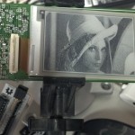
    ereader.display_wif("/IMAGES/LENA.WIF", -264/2, 0);
    ereader.display_wif("/IMAGES/LENA.WIF", 264/2, 0);
  }
  else{
    ereader.display_wif("/IMAGES/AANDJ.WIF", -264 / 2,  176 / 2);
    ereader.display_wif("/IMAGES/AANDJ.WIF",  264 / 2, -176 / 2);
    ereader.display_wif("/IMAGES/CAT_SM.WIF", 264 / 2, 176 / 2);
    ereader.display_wif("/IMAGES/APHRODIT.WIF", 0, 0);
    ereader.toggle_ellipse(random(0, 264), random(0, 176), 20, 20);
    ereader.put_ascii(random(0, 200), random(16, 150), "WyoLum ROCKS!!", true);
    ereader.setpix(128, 0, true);
    ereader.setpix(128, 2, true);
    ereader.setpix(128, 6, true);
    ereader.put_unicode(10, 140, UNICODE_MSG, true);
    ereader.toggle_line(70, 0, 120, 50);
  }

  loop_count++;
  ereader.show();
  ereader.sleep(1000); // allows EPD to power off gracefully
}

Function descriptions
The first call you need to make on the global epaper variable is the setup method. This call takes a single argument that indicates one of currently three possible sizes: (small)EPD_1_44, (medium)EPD_2_0, and (Large)EPD_2_7.

  void setup(EPD_size size);

Zero out the frame buffer to clear the display. You should not have to call this method explicitly. It is called after each show() in preparation for the next image. Each frame begins blank by default.

  void clear();

Display a WIF image at the indicated x,y location. Partial images will be displayed by using negative x and or y coordinates.  Path is the full path to the file, like “/IMAGES/AANDJ.WIF” for instance. Use the old 8.3 naming convention to save your self hassle.

  bool display_wif(char *path, int16_t x, int16_t y);

Set a pixel located at x, y to indicated val: true=black, false=white.

  void setpix(uint16_t x, uint16_t y, bool val);

Toggle the pixel located at x, y. If the pixel was white, it becomes black and vice versa.

  void togglepix(uint16_t x, uint16_t y);

Draw a line from staring x,y to stopping x,y in indicated color:true=black, false=white.

  void draw_line(int16_t startx, int16_t starty, int16_t stopx, 
                 int16_t stopy, bool color);

Draw a line from staring x,y to stopping x,y by toggling each pixel on the path.

  void toggle_line(int16_t startx, int16_t starty, int16_t stopx, 
                   int16_t stopy);

Draw an ellipse centered at cx,cy with x-radius rx and y-radius ry in the indicated color:true=black, false=white.

  void draw_ellipse(uint16_t cx, uint16_t cy, uint16_t rx, 
                    uint16_t ry, bool color);

Draw an ellipse centered at cx,cy with x-radius rx and y-radius ry by toggling each pixel on the path.

  void toggle_ellipse(uint16_t cx, uint16_t cy, uint16_t rx, 
                      uint16_t ry);

Draw a single unicode character at location x, y in the indicated color:true=black, false=white. Location is the upper left hand corner of the character bitmap.

  uint16_t put_char(uint16_t x, uint16_t y, uint16_t unic, bool color);

Put either an ASCII string (one byte per char) or a unicode string (two bytes per char) at the specified location and color:true=black, false=white.IMG_20130516_185849_504

  uint16_t put_ascii(uint16_t x, uint16_t y, char * ascii, bool color);
  uint16_t put_unicode(uint16_t x, uint16_t y, uint16_t * unic, 
                       bool color);

Read the width and height dimensions of a WIF image stored in the provided File using “pass by reference”.

  void SD_image_dims(File imgFile, unsigned short *h, 
                     unsigned short *w);

TODO:

  • Filled rectangles, ellipses
  • update EPD.h to handle partial updates
  • hack EPD.h for 4-bit grey scale.


Epoch: $10 Real Time for RaspberryPi

Epoch01_02

(This post is a re-write of the easy to follow instructions  and more instructions available from AdaFruit.com with some original added python stuff.  Thanks AdaFruit!)

If your RaspberryPi project needs to know the date and time without an internet connection you need a real time clock.  There are a few available.  The cheapest option is AdaFruit’s DS1307 kit at $9.00.  This kit works with Arduino and Raspberry pi if you are willing to put it together.

Epoch is a real-time clock designed just for the Raspberry Pi.  It attaches right to the GPIO, no assembly required.  We’ve priced it without a middleman markup so we could keep it as cheap as possible.

Here is how I got my Epoch Prototype up and running.  I started with a fresh raspian installation to be sure I did not miss any steps.  I’ve done this all form the command line.  Use LX terminal or SSH into your pi.

Screenshot from 2013-05-11 17:13:43

You can see that although the rtc is present, it is not yet available.  First we have to get the tools to talk to I2C.

> sudo apt-get update
> sudo apt-get install git
> sudo apt-get install python-smbus
> sudo apt-get install i2c-tools

Now let’s make sure the I2C is not blacklisted.  Edit the /etc/ /etc/modprobe.d/raspi-blacklist.conf file.  Comment out the last two lines if this file is present.

> sudo nano /etc/blacklist.confScreenshot from 2013-05-11 17:22:22

Next we have to enable I2C on the pi by editing the /etc/modules file. Add the following lines and reboot.

i2c-bcm2708
i2c-dev

> sudo nano /etc/modules

Screenshot from 2013-05-11 17:15:51

> sudo reboot

Now see what is on the I2C bus (bus 1 for newer raspberry pi models 0 for older ones)

> sudo i2cdetect -y 1           ## use -y 0 for revAScreenshot from 2013-05-11 17:23:49

And the is the DS3231 chip showing up at address 0x68!

Next let’s install the python interface to this chip (not required: skip to hwclock setup if you don’t need python interaction with the rtc)

I just created a directory called GIT on the pi to download the Epoch library into.  You can put it wherever you want.

> mkdir GIT
> cd GIT
> git clone https://github.com/wyolum/Epoch.git
> cd Epoch
Screenshot from 2013-05-11 19:36:18

It works!

hwclock setup (skip to here)

Most likely you will want to operating system to control the hardware clock.  This takes a few steps to set up.  Type the following from the command line.  The greater than symbol “>” represents the pi user, whereas the pound sign “#” represents the root user command prompt

> sudo bash
# modprobe rtc-ds1307
# echo ds1307 0x68 > /sys/class/i2c-adapter/i2c-1/new_device
# nano /etc/modules

(add the line “rtc-ds1307” and save the file)

Screenshot from 2013-05-11 18:09:01(while still root user add the following two lines to /etc/rc.local and save)
echo ds1307 0x68 > /sys/class/i2c-adapter/i2c-1/new_device
sudo hwclock -s

nano /etc/rc.local

Screenshot from 2013-05-11 18:10:20Now reboot and test it out

# reboot

(…after logging back in.  If you are not connected to the internets set the time manually)

> sudo date –set=”20130511 02:08:00″ 
> sudo hwclock -w
> date

Screenshot from 2013-05-11 22:15:33

Introducing WIF: the WyoLum Image Format.

I love the new e-paper offered by Pervasive Displays and sold by AdaFruit.  They are a bit tricky to get started with however.  By default, they only display images, no text or standard graphics calls like “line” and “circle” and each image takes a lot of memory.  Too much for a stand alone Arduino UNO.

Even if you have the memory, another tricky thing about them is getting an image to look good in pure black and white (no greys).

At WyoLum, we have tackled all of these problems and figured out how to display UNICODE chars, and draw graphics (lines and circles).  We’ve chosen to use an SD card as both a file source and a screen buffer.  It is working well.  Most of this is just in test code state, but we figure there are others out there struggling with the same issues and might find our solutions handy.

Quick Start:

  1. Crop images with Inkscape and export as png
  2. Convert png to WIF in IMAGES directory on SD card
  3. Load AlaModeEPD on your SD extended Arduino (we use AlaMode of coarse)

Slow Start:

The subject of this post is the WyoLum Image Format, as well as how to create and display images on  repaper displays.  This binary format is nearly a direct translation of the XBM format except rather than C-code written in ASCII, it is binary.

The first two bytes are the image pixel height as an unsigned integer in “little endian” format (least significant byte first).  The next two bytes are the image pixel width as an unsigned integer again little endian.  The remaining bytes contain the pixel data, row by row.

I’ve written a little python program called greyscale.py to convert standard image files into WIF.  It is a bit of a misnomer to call it “grey scale” as each pixel is either black or white.  Greys are created with varying densities of dark pixels.  This is a non-trivial task.  I love how the Python Image Library makes this so easy.  To use it, first resize  your image with your favorite image editor to the correct size for your e-paper display:

1.44" --> W=128 and H=96 (pixels)
2.00" --> W=200 and H=96
2.70" --> W=264 and H=176

Inkscape, or Gimp work great for this. I’ll use Inkscape for this example.

Screenshot from 2013-04-29 22:00:27After starting Inkscape, open your document properties found under the file menu.  Set the width and height to the pixel size for your display in the “Custom size” box.  Now draw a hollow box the fills the entire page.  This box is used to center the area of interest in the display area.  (Note that when the box is selected you can use the text entry fields on the top labeled “W” and “H” to get the exact size on the box in pixels.  Set x and y both to 0).  If your box is filled in, you can hollow it out by clicking the “X” above “Fill” in the lower left hand corner of the window.Screenshot from 2013-04-29 22:07:40

Now find an image you’d like to convert.  I will use Lena, an image processing classic for it’s rich mixture of high and low frequency content, lights, darks and greys.  Use “File–>Import” to load your image.  Select “embed” when the dialog pops up and click “ok”.Screenshot from 2013-04-29 22:15:08

There are two things wrong here: we’ve hidden the page size and the image starts off too big.  To push the image to the bottom of the object stack, press the “end” button on your keyboard.  Then, with the aspect ratio lock closed (top center of GUI) re size the image for the display.  Make sure you move the image and not the box.Screenshot from 2013-04-29 22:20:50

Now export the page using “File–>Export Bitmap”.  Click “Page” to export only the page area, make sure the Width and Height are correct, type a filename and click “Export”.  If you use the “Browse” button, you still have to click “Export” after you have selected your filename.Screenshot from 2013-04-29 22:24:25

Now start greyscale.py using the command “python greyscale.py” on the command line or double clicking the filename.  You will need to have the Python Image Library installed in your python distribution  (try Enthought Canopy distro if you are starting from scratch for one click install).  An empty canvas should pop up.Screenshot from 2013-04-29 22:28:44

Use the “File->Open” menu command to find the file you just created.  LENA3.png in my case.  Adjust the target size from the “Size” menu.  Adjust the Contrast and Brightness sliders until you are happy with the result.Screenshot from 2013-04-29 22:32:41

Save the image in WIF using the “File–>Save” menu item.  Your files should conform to the old 8.3 dos filename format (HAPPYDAY.WIF for instance) to avoid FAT hassles.  The greyscale.py program will do its best to help you on this.  Repeat the process with as many pictures as you want.

Display the Images

Aside from the repaper breakout board, you will need an Arduino set up according to the display Pin Assignment and an SD shield (AlaMode with onboard uSD slot works great for this ;-)).  Copy all of your newly created “WIF” files into a directory called “IMAGES/” on your SD card.  And load this demo program from the Arduino environment.

T-Slot Boxmaker

t-slot-box

Laser cut boxes are pretty cool.  They can be tricky to design however.  “Maker” has taken a lot of the guesswork out of making boxes with a cool Inkscape extenstion.  Its written in Python, so Anool challenged me to add t-slots so that the resulting boxes can be held together with screws instead of glue.

It took me a while to wrap my head around the whole extension business.  It is not pretty, but I finally managed to cobble together the necessary parts to get this working.

USE IT:

  1. download code and unzip it into your Inkscape extensions directory.  On my Ubuntu laptop that is /usr/share/inkscape/extensions/.
  2. Start or Restart Inkscape.
  3. Select T-Slot Box Maker from the Extensions->Laser Tools menuScreenshot from 2013-03-27 19:35:30
  4. Insert your box measurements and screw measurements (so far only tested with 16mm M3 screws.Screenshot from 2013-03-27 19:38:27
  5. Click “apply”
  6. Remove unwanted or conflicting t-slots with the associated holeScreenshot from 2013-03-27 19:42:30
  7. Done!  Good luck!Screenshot from 2013-03-27 19:43:57