 A couple of weeks ago, I noticed a pair of old, first version TiM boards lying around at my local maker space, Maker’s Asylum and decided to put them to use by building a MoodLight. We love crazy names at WyoLum, and TiM is “The Intelligent Matrix”. We even tried building a controller for it called TiNA but it didn’t work out 🙂
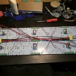
 TiM (The intelligent Matrix) is an array of 8×16 individually addressable 5050-WS2811 RGB “smart” pixels. It is essentially 8 rows of 16 LED’s but with a very flexible connection scheme that allows you to control the whole array (128 LEDs) with a single pin or up to 10 boards (1280 pixels) chained together using 8 input pins. TiM boards can be linked together to create larger matrices. Stacking can be done in the vertical and horizontal orientations, and the pitch between individual LEDs is maintained when boards are stacked. Here’s the TiM User Guide.
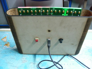
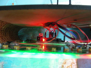
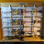
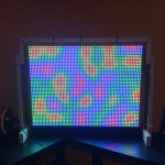
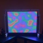
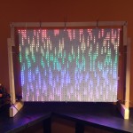
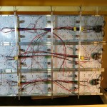
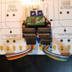
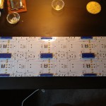
 I had two boards on hand, which I joined together to form a 16×16 matrix of 256 LEDs. TiM boards need an external controller, and I used an Arduino Clone that I designed for use at the Maker’s Asylum called MAPone (Maker’s Asylum Project #1). MoodLights require some form of user interaction, and I decided to use one push button (digital input) and one potentiometer (analog input). The whole thing is powered by a 5V wall wart.
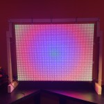
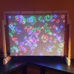
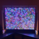
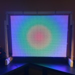
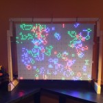
 For the software, I tried some code I found on the web, but none of it did what I wanted – change modes by pressing the button, and change colors using the potentiometer. I can’t code if my life depended on it, so I chucked the problem at my go-to guys – Justin and Kevin. Justin is quick, like the Energizer bunny, and threw back code at me on the rebound. But it required using four potentiometer’s to control the colors. Since the HW was already wired up, I waited to see Kevin came up with something different, which he did. Nice code which allowed different modes to be selected by a button press. The first mode is the standard Rainbow colors from Adafruit’s StrandTest. Then, there’s a color changing mode, Breathing LEDs, Connection Machine (which looks something like Conway’s Game of Life), and finally a scrolling Text mode. This is enough to start with, and I’m sure if anyone at the Asylum wants to hack and dig in to the code, there’s a lot for them to play around with.
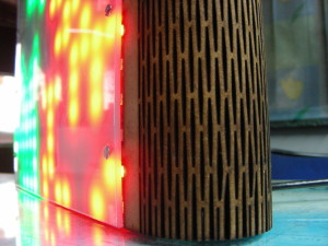
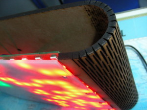
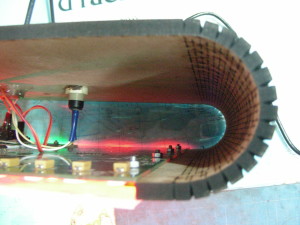
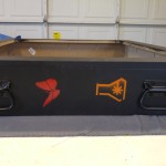
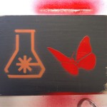
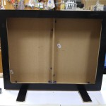
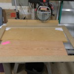
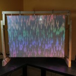
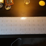
 I designed the enclosure in OpenOffice Draw. A laser cut piece of MDF that wraps around the TiM PCB using some “living hinge” bends. I tried some junked 3mm MDF first, but the material was kinda bad – some parts cut well, while other areas were left with a charred and burnt top layer, so I had to scrap that. Next, I tried 5mm MDF that way lying around, and while it cut well, it was a tad thicker than I preferred and the hinges were stiffer being designed for thinner 3mm MDF. Anyhow, it worked and I was keen on just finishing this off. I also cut an additional square piece of 2mm white polypropylene sheet for the front diffuser. Most of the electronics was stuck in place using generous globs of hot glue. I added some hand drawn graphics to wrap it off, and left it at the asylum. Let’s see how they mount it up.
Here’s a video walk through of the MoodLight.
EDIT : Here’s a better walk through of the code by Kevin Osborn