Announcement: I2SD, A disk drive for Arduino

WyoLum is proud to announce I2SD which provides disk drive storage to your Arduino based project.

I2SD is an I2C interface for an SD card compatible with ClockTHREE and ClockTHREEjr.  The idea behind I2SD is to allow easy read/write access to files stored on an SD card.  If the I2C bus is already part of a circuit, I2SD does not require any extra pins, therefore optimizing pin usage on the micro.

Thanks to AdaFruit and SparkFun for sharing there SD designs!

Why I2SD? Good question!  After all there are a few boards that allow you to connect an SD card to your project: AdaFruit’s data logging shield, and SparkFun’s MicroSD shield are two stand outs in this category.

There are three reasons you should consider I2SD:

  1. ATMEGA328 memory limitations.
  2. ATMEGA328 pin count.
  3. You want a small form factor stand alone data logger.

On ClockTHREE we are both pin count and memory limited and we wanted to be able to store lots of cool animations.  We designed for the stand alone data logger as a target of opportunity.


The next rev will sport optional locations for an RTC chip and battery back up.
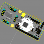
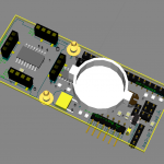
Details

Components:

  • ATMEGA328
  • SD card
  • 2 LEDs
  • ChronoDot or DS3231 (optional)
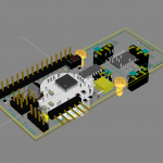
Interfaces:

  • 6-pin ISP
  • FTDI
  • 2x C3SB (see below)
  • Buckler (see below)

Using I2SD from an Arduino Master (Buckler interface see below)

Currently there are five methods implemented for simple file reading and writing.

  ping(uint8_t* ping_data, uint8_t n_byte);
  seek(unsigned long addr);
  open(char* filename, uint8_t mode);
  read(uint8_t *data, uint8_t n_byte);
  write(uint8_t *data, uint8_t n_byte);
Which can be used to read and write a small file:

 //Write a file
 i2sd.open("NEW_FILE.TXT", FILE_WRITE);
 char* msg="Hello from I2SD_Client.pde. "
           "Please note this is longer than 32 chararters.";
 i2sd.write((uint8_t*)msg, strlen(msg) + 1);

//Read it back
 i2sd.open("NEW_FILE.TXT", FILE_READ);
 uint8_t msg_back[100];
 unsigned long n_byte = i2sd.read(msg_back, 100);
 msg_back[n_byte] = NULL;
 Serial.println((char*)msg_back);
 write(uint8_t *data, uint8_t n_byte);

C3SB (preview)

This is the first peripheral to implement the ClockTHREE Serial Bus interface which deserves a post of its own (coming).   Its like USB for Arduino which allows the connection of many peripherals without increasing pin usage.  C3SB is build on I2C


C3SB physical interface, 4 pins with 0.1″ spacing:

  1. VCC — 5V min 100mA
  2. SCL — I2C Clock pin
  3. SDA — I2C Data pin
  4. GND — +0V

C3SB software Master interface:

I2C transfers are limited to 32 bytes.  The C3SB allows up to 255 bytes by breaking them up to 32-byte I2C packets for you.  Two read/write functions.

uint8_t read_from(uint8_t device_id,
                  uint8_t* dest,
                  uint8_t n_byte);

boolean write_to(uint8_t device_id,
                 uint8_t *payload,
                 uint8_t n_byte);

Buckler form factor (preview)

A “buckler” is a small shield, 15 to 45 cm (6 in to 18 in) in diameter , gripped in the fist (From Wikipedia).  I2SD is a small shield so we thought this was a clever name for this form factor.

ClockTHREE_connect

So here is the problem: How do we ship ATMEGA328 chip, with ClockTHREE pre-installed, AND allow someone to test each column of LEDs as they build it up? ClockTHREE_connect a “pre-alpha” suite of three interconnected tools that provide an interface between a computer and ClockTHREE: C3_interface.py which is the low level python interface, C3_GUI.py a graphical interface for setting alarms, and ClockTHREE.py a computer based ClockTHREE mirror.

ClockTHREE.py is what I want to introduce here. This program drives the LEDs on an actual CLockTHREE.py through the serial interface.

Here is how to use it (to test LEDs or expand it to do other cool stuff).

  • Download and unzip ClockTHREE_connect.zip.
  • Plug in your ClockTHREE to a wall outlet and int a computer with the included FTDI cable.
  • Double-click C3_GUI.exe in the newly created ClockTHREE directory.  When the program comes up, the serial port box should default to some value.  In my case it is COM7.
  • Click the “Connect” button.
  • The MirrorC3 button should become enabled, click it to bring up the ClockTHREE mirror.
  • Type the “t” key on your computer keyboard.  This will start a sequence of alternating colors on both the mirror and you ClockTHREE.
  • Type “t” again to stop the sequence.
  • Try typing the number “2” on your keyboard (my favorite).
  • Experement, what else would be cool?  Email, Stock ticker?

WiseClock3 Review

In between working on ClockTHREEjr, I have been experimenting with the WiseClock3.

Emily soldering the WiseClock3. You can see we were in the middle of ClockTHREE assembly when our WiseClock3 arrived. We took an hour off to build up WiseClock3 to provide us with the wisdom we needed to complete our ClockTHREE commitment.


The board was a snap to assemble, it took Emily (an expert solderer) less than an hour from start to finish.  Usually, the real-time clock chip comes pre-soldered which leaves only a couple dozen through-hole parts to solder. Emily actually soldered the surface mounted clock chip on ours since Florin was out of them when we ordered.   The assembly was very easy and would make a great second soldering project.  If you are interested in making a clock, but have never soldered before,  get a couple of cheaper soldering kits to get confident with, before you dive into a WiseClock3.  For instance,  we had great fun with the Larson Scanner Kit from EvilMadScience.com.

Once the soldering is complete,  the WiseClock3 board plugs into an included display from Sure Electronics.  This is a very cool product in and of itself: it provides an array of 16×32 RED-GREEN LEDs that can be individually controlled.  That is a lot of LEDs in a small space.  Just compare it to the ClockTHREE which is about 9 times larger in area, yet has only a quarter as many LEDs.

WiseClock3 packs in 4 times as many LEDs in 1/9th the area!

Finally we screwed on the simple but elegant acrylic enclosure and plugged it into an available USB port and voila: live streaming pithy quotes delivered directly from the SD card.

Fine, the WiseClock3 works great as is.  But is it hackable?  Indeed!  Florin provided programming access though an FTDI interface and an ISP interface. With just a little effort I was able to run code that I had developed for ClockTHREE.  One program that I had great hopes for with ClockTHREE is called “Night and Day”.  It shows where the sun is shining right now, all over the planet.  With only a 12 x 16  array of LEDs to work with on ClockTHREE, the resolution left a lot to be desired, but that same code looks great on the WiseClock3 (see above).  Florin provides an easy function for setting the color of each pixel, so it was just a matter of linking in the counterpart method from ClockTHREE.  I haven’t played with them yet, but he also provides functions to stroll or set text in small or large fonts.

Florin chose the ATMEGA644 as the micro controller because it has Arduino support, and beaucoup progamming memory, twice that of the Arduino Uno.  I was running into that barrier while programming ClockTHREE and would gladly use the extra space.

The bottom line is that this is a great project for anyone with even a little soldering experience.  It comes pre-programmed, but has plenty of hacking potential.

Keep up the good work Florin!


Look here for more pictures of our WiseClock3 and vid: