‘Alamode is on the way!


Kevin has been working night and day to fully test the Alamode design.  The design passed with flying colors.  My SMD workmanship failed miserably though!  We believe the failure mode on some of the sample boards is overheating of the 3v to 5v level shifter during installation.  Both Kevin and Anool managed to assemble without destroying the level shifter.  My hats off to both of them.

The test fixture pictured above deserves its own mention.  This is made up of a 3.3v Mega Pro from Sparkfun, with their (pathetic aaarg!) Mega Shield and the Seeed TFT Touch ($35!) shield on the top.  The complete test procedure is available GitHub, but it all boils down to happy and sad emoticons.

We will have the Alamode available for pre-order as soon as we hear back on expected delivery date.

GPS over I2C!


We’ve written a simple I2C interface for I2GPS (available for sale here). If you’ve ever combined GPS to Arduino you have probably used TinyGPS by Mikal Hart.  We use it too and we love it.

When you want to incorporate GPS into a larger project a couple of issues arise that I2GPS solves.  The first issue is that the GPS object must constantly be “fed” new data.  This leads to ubiquitous calls to gps.feed() throughout the code.  If you have other time critical functions (like updating an LED matrix), the juggling of tasks can get overly complex.  The second is the size of the code can cramp the size of your main program.  We ran into both of these problems with ClockTHREEjr.

I2GPS solves these problems with by offloading the memory and processing burden to a second processor.  The I2GPS slave code needs only to read the GPS, and respond to I2C requests to data.

I’ve modeled the interface after the DS3231, the real time clock included with I2GPS, the same clock as the Chronodot from Macetech.  So from the client side, things look a lot like reading the Chronodot.  Here is a snippet of client code (not updated).  The DS3231 is still available though the I2C interface.

// read 32 bytes from address 0, store in "gps_data" byte array
  gps_raw_read((uint8_t)0, (uint8_t)32, gps_data);

// Parse response
  Serial.print("UNIX TIME:");
  Serial.println(unserialize_ulong(gps_data+0));
  Serial.print("LAT:");
  Serial.print(unserialize_long(gps_data+4));
  Serial.println(" 1/1000th DEG");
  Serial.print("LON:");
  Serial.print(unserialize_long(gps_data+8));
  Serial.println(" 1/1000th DEG");
  Serial.print("ALT:");
  Serial.print(unserialize_long(gps_data+12));
  Serial.println(" CM");

Wall clock time is also available starting at address 0x1C.

gps_raw_read(0x1C, 6, ymdhms);

Serial.print("CALENDAR TIME:");
Serial.print(ymdhms[1], DEC); // Month
Serial.print("/");       
Serial.print(ymdhms[2], DEC); // Day
Serial.print("/");
Serial.print(ymdhms[0], DEC); // Year

Serial.print(" ");
Serial.print(ymdhms[3], DEC); // Hour
Serial.print(":");
Serial.print(ymdhms[4], DEC); // Minute
Serial.print(":");
Serial.print(ymdhms[5], DEC); // Second
Serial.println("");

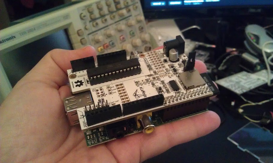
The I2GPS has several physical interface options. Shown above is the “Buckler” (small shield) interface that plugs directly into the analog side of the Arduino.

The complete data structure memory map is available as a google spreadsheet (for the latest) or below in static html.  I’ve put a couple of field to log the state of analog and digital pins, but supporting code has not been implemented yet.  Available data include: unix time (and wall clock time), latitude, longitude, altitude, course, speed, fix age.


Programming ClockTHREEjr_v2

At some point, you may wish to re-program your ClockTHREEjr_v2 or maybe you are building a clock from scratch.  This post will walk you through the steps.

Outline:

  1. Download and install Arduino for your target platform.  (More details can be found here.)
    • Navigate to the Arduino download site: http://arduino.cc/en/Main/Software
    • Download Arduino for your platform.
    • Unzip the file to the directory of your choice.  (We will refer to whatever directory you choose as <arduino_dir>).  I use c:\arduino\ on Windows or /home/justin/arduino/ on Linux so that (for arduino 1.0 for instance) the path extracted executable is c:\arduino\arduino-1.0\arduino.exe on Windows or /home/justin/arduino/arduino-1.0/arduino on Linux.
  2. Download and install ClockTHREE source code
    • Download the latest ClockTHREE library source code file from here: http://code.google.com/p/clockthree/downloads/list
    • Unzip the library source code file in your home directory. I use “My Documents\sketechbook\” on windows and /home/justin/sketchbook/ on linux.  We will refer to the directory you choose as <sketchbook>.
  3. IMPORTANT: Point Arduino to your newly extracted library files.
    • Start arduino (look here if you have trouble with this step)
    • Click File->Preferences to pull up the preferences menu.
    • Leave “Use external editor” unchecked if you plan on using Arduino as your editor.
    • Click the “Browse” button and navigate to your <sketchbook> directory from step 2.
    • Click “OK”.
    • Close and restart Arduino
    • Click “File->Sketchbook->libraries”.  If “ClockTHREE” is listed you’ve done well.
  4. Using a text editor, edit source code:
    • On or about line 32 of <sketchbook>/libraries/ClockTHREE/examples/ClockTHREE_04/ClockTHREE_04.ino, comment out all but one of the following lines depending on language and hardware.
    // #include "dutch_v1.h"
    // #include "english_v0.h"
    // #include "english_v2.h"
    #include "english_v3.h"
    // #include "french_v1.h"
    // #include "german_v1.h"
    // #include "german_v3.h"
    // #include "german_v5.h"
    // #include "hebrew_v1.h"
  5. Compile and upload
    • Connect the FTDI cable to ClockTHREE (mind color labels) and to your computer.
    • Click Tools->Boards->Duemilanove
    • Select USB port Tools->Serial Port (this may take some trial and error if you have several devices connected).
    • Compile and upload <sketchbook>/libraries/ClockTHREE/examples/ClockTHREE_04/ClockTHREE_04.ino.
      Click the arrow button, second from the right.  
  6. Congratulations!  That is it.  Now you can customize the code to your hearts content!

Arduino and Python

Arduino fans take a lot of flack from the “hard core” micro-controller crowd.  The main complaint is that many projects could be accomplished much more simply.  Take “blink” for example.  Why would you use and Arduino to blink an LED when you can accomplish the same with a 555 timer?  This criticism is eerily similar to complaints I’ve heard about the programming language Python.

Now, Python is a well accepted language that has proliferated into every aspect of computation form the Web, to scientific computing, to graphics to … you name it.  But this was not always the case.   I’ve experienced many eye-rolls and many doubters throughout my twelve year experience with Python.  But Python survived them all because of its massive utility.  Programmers are simply more productive with Python and the economics finally won out.  You can do more in less time with Python.

Arduino faces a similar challenge.  It is disruptive to the status quo and enables anyone with even a passing interest to get something working in electronics with no background and very little effort.  With effort, those same people can accomplish amazing things using Arduino.

To say that “Arduino is overkill” misses the point!  It is often a choice between getting something done or not.  The less time something takes, the more you can accomplish.  And, if Arduino is capable of a task then it is the fastest way to get it done (for me at least).

This brings me to à la mode.  If you have not heard, à la mode is an Arduino compatible board that mates with the Raspberry Pi single board computer.  The R. Pi is a computational powerhouse compared to the Arduino, but it lacks the analog interface to interact with the real world that Arduino has.  Better yet the Raspberry Pi à la mode combo will allow me to mix my two favorite programming languages: Python and Arduino!

I am planning to write a program for à la mode that provides an I2C interface to all of the functionality that the à la mode has to offer.  When both sides of the interface are complete, it will be very simple to read and write analog or digital pins, read the real time clock, and get GPS position (optional).

I can’t wait to get my hands on the hardware!

Customer Photos!

Until we set up a flicker (or whatever those kids are using these days) gallery, we can post user photos emailed to me here.