The first week of January had me and Samata Mahidharia driving down to Ahmedabad, about 550 kms North of Mumbai. We were on our way to attend MakerFest 2014, organized by the awesome folks at Motwani Jadeja Family Foundation, at the uber-cool design school – National Institute of Design.
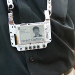
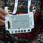
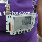
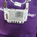
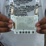
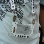
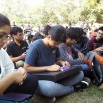
WyoLum gave away 40 of our BADGEr – e-paper conference badges for Makers attending the Maker Fest. We didn’t have time to program all the BADGEr’s , but the Makers were kicked to be able to take them away and get hacking. I took a few pictures.
-
-
-
-
-
-

-
-
BADGEr spottin’ at MakerFest 2014
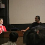
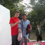
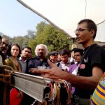
I gave a talk about the Maker Movement – talking about how the Maker revolution is bringing us back to our Maker roots, using my personal experiences as examples.
-

-

-
-
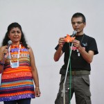
talking about the Maker Movement
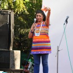
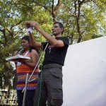
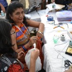
Samata and me did an Origami Workshop. The initial plan was to limit attendance to 20 people in a classroom. Eventually, a much larger number of people turned up, and the organizers asked it we could accommodate all. Seeing as how enthusiastic everyone was, we just couldn’t refuse, and moved our workshop to the main stage of the open grounds. It was wonderful to be surrounded by almost 50-60 folks – from little kids to grown ups, eager to learn some folding. Due to the large crowd, and also that no one had a good flat folding surface in front of them, we cut down the original plan of folding about 6-7 models in an hour to a more manageable 3 simple models. Eventually, I think everyone managed to fold the models – a tumbling toy, a cawing Crow and a Swan.
The most exciting event for Samata and Me was to team up with Albie Brown and run a MakerFest Treasure Hunt. Up for grabs was a bag full of goodies, including a WyoLum BADGEr, a BeagleBoneBlack and other cool stuff.
Visitors to the Fest were handed over a “Guide for Hunters”
This explained how the hunt worked. On the back of the sheet was a list of 100 words, numbered 00 – 99. Only five of these were relevant to the final solution of the puzzle, the remaining 95 being duds. Hunters were asked to stroll through the booths at Makerfest 2014, where they had to find, and solve, five mini puzzles.
The starting “hint” was that there were a few logos on the clue sheet that indicated which booths are presenting challenges. In no particular order the five booths were:
Education for Design (e4d)
Microsoft Research
WyoLum
FabLab
Printajoy
E4D is working towards bringing education to everyone. Beginning with a handful of Centres in southern India, they are building a higher educational model focused on reaching the masses, rather than building universities. They seek to minimize infrastructure and costs, while taking full advantage of freely available online educational resources. Their activities also include education for blind persons. Their clue was – What is the name of this code spelled backwards? This hint was written in braille on a piece of a can and the can was glued to a stick of bamboo. Puzzlers had to translate the braille and answer the question to solve the clue. The answer was “elliarb”
Microsoft Research is working on conductive ink printers made from regular Ink Jet Printers, but using special cartridges filled with ink made from Silver nano-particles. These printers, along with a range of sticker adhesive elements, allows designers to quickly fabricate prototypes. Their clue was – “What am I made of? (Hint: they sometimes call me 47)” and the answer was “Ag” (the symbol for silver).
WyoLum put up one of their ClockTHREEjr with a code written next to the clock – C1F8D1H1N9G6. Reading off rows and columns (C1, F8 etc) gave them the word “Patang” which translates in to English as “Kite”
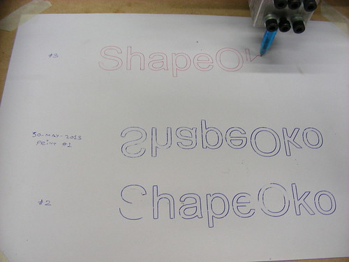
The MJFF donated a $140,000 Fablab from MIT to the maker community in Ahmedabad. The Fablab is a set of digital fabrication equipment and software to help makers transform their imagination into products. The Fablab is housed at the prestigious CEPT University Ahmedabad and will be open to the public at select hours every day. At the Fab Lab booth the manager told puzzlers to press print. They had to figure out how to use the vinyl cutter and print a document that was concealed by coloring all components black so the text was invisible. The machine then cut out the word “Replicate” in sticker form and the puzzlers had to pull off the sticker to reveal the answer.
Printajoy is a photo printing service for Instagram photos – a “Print button for your Instagrams” India’s first affordable, online printing solution that converts your Instagram photos into beautiful lifetime memories! Their clue was – “There is something hidden underneath every Smile”. Then under the deck of business cards (which said smile on the front) there was one card with a label with the word “Memories” stuck to it.
If you solved all five puzzles you ended up with five answers and five two digit numbers. Several teams kept asking us to check if they’d got all the right words, but we just encouraged them to continue going.
At 3:30 we revealed the final clue. Albie wrote out the clue on a white board, and held it up for everyone to see
_ _ _ _ _FEST
The first alphabet taken from each our five answers, when placed in the right order formed the word MAKER. Almost everyone filled in the blank with “MAKER” but were flummoxed when we encouraged them to keep going since the hunt was not yet done. The smart winning team realized very quickly that the numbers still have not been used. “MAKER” indicated the order in which to use the 10 digits, which gave a phone number. When they called the number, they won!!! The winning team called the phone number within a minute of our releasing the final clue. Not just that, they even followed Albie who ran behind the stage when he picked up the phone they had dialed, and told Albie – “Turn around and look here – I’m the guy calling you”
In the middle of the Maker Fest grounds, we set up a pop-up Maker Space where the makers got together and started building and showing off stuff to visitors, and encouraging them to join in. There was a lot of Arduino, flexible sticker circuits, wearable electronics, PVC pipe Lamp shades and other stuff going on. Samata even stitched a quick Dress from an old Saree and sewed a string of LED’s around the neck. Apparently she did a Ramp Walk with the LED dress in the auditorium, but I wasn’t around to witness the awesomeness !
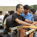
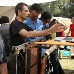
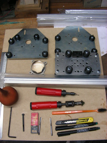
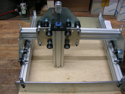
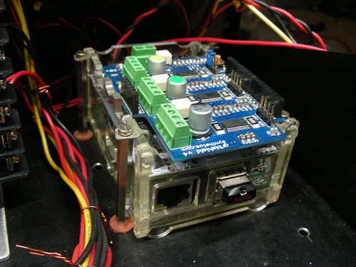
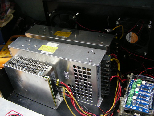
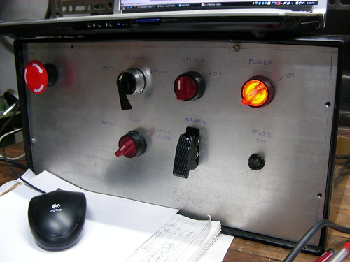
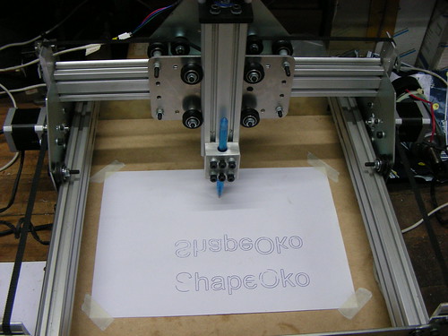
I set up a PolarGraph drawing robot. I had received the kit a few days before heading off for MakerFest, and had no time to get it working. At the Makerspace, I tried setting it up, and even managed to get one trial print. But I was constantly being interrupted by eager visitors asking me what it was, and ended up spending all my time telling them what it was supposed to do. I even managed to show it off to Mr. Sam Pitroda
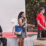
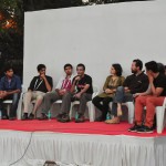
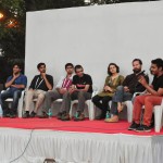
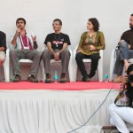
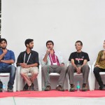
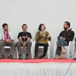
At the end of the second day, the MakerFest was wrapped up with a Panel Discussion featuring a bunch of Makers – Angad Daryani – a young Maker from Mumbai , Spandana Cheruvu – another young maker , Anand Gandhi – Ship of Theseus film maker , Freeman Murray from Jaaga Bangalore, Anna Waldman-Brown curator of MakerFest 2014 , Myself, Vaibhav Chabbra – from the EyeNetra team and also running Makers Asylum in Mumbai, Ankit Daftary – from the Arduino India team, Bangalore , and Kshitij Marwah from MIT Media Labs
Thanks to everyone who participated! We had a great time putting it all together! We met some amazing Makers from all of India. Some of them we knew via Facebook or Twitter or Google, but meeting them in person was wonderful. And we made a lot of new friends ! All in all, this years MakerFest was a blast and we look forward to next year’s MakerFest.


 A couple of weeks ago, I noticed a pair of old, first version
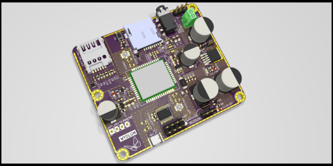
  TiM (The intelligent Matrix) is an array of 8×16 individually addressable 5050-WS2811 RGB “smart” pixels. It is essentially 8 rows of 16 LED’s but with a very flexible connection scheme that allows you to control the whole array (128 LEDs) with a single pin or up to 10 boards (1280 pixels) chained together using 8 input pins. TiM boards can be linked together to create larger matrices. Stacking can be done in the vertical and horizontal orientations, and the pitch between individual LEDs is maintained when boards are stacked. Here’s the
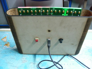
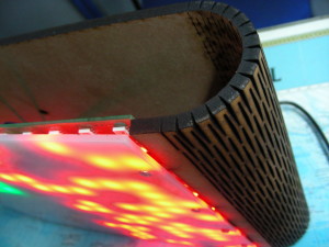
  I had two boards on hand, which I joined together to form a 16×16 matrix of 256 LEDs. TiM boards need an external controller, and I used an Arduino Clone that I designed for use at the Maker’s Asylum called
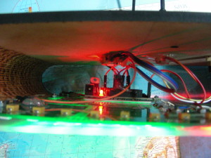
  For the software, I tried some code I found on the web, but none of it did what I wanted – change modes by pressing the button, and change colors using the potentiometer. I can’t code if my life depended on it, so I chucked the problem at my go-to guys – Justin and Kevin. Justin is quick, like the Energizer bunny, and threw back code at me on the rebound. But it required using four potentiometer’s to control the colors. Since the HW was already wired up, I waited to see Kevin came up with something different, which he did. Nice code which allowed different modes to be selected by a button press. The first mode is the standard Rainbow colors from Adafruit’s StrandTest. Then, there’s a color changing mode, Breathing LEDs, Connection Machine (which looks something like Conway’s Game of Life), and finally a scrolling Text mode. This is enough to start with, and I’m sure if anyone at the Asylum wants to hack and dig in to the
  I designed the
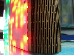


cYvbwzg~~60_12.JPG)