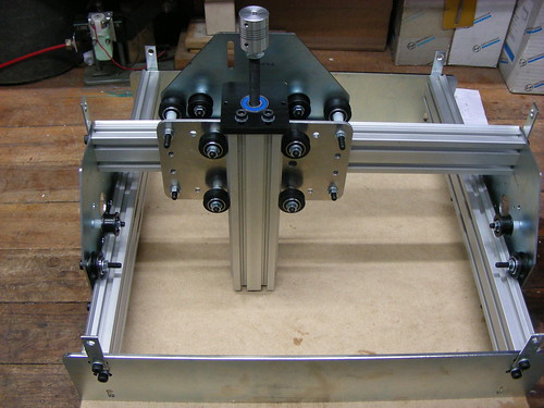
Well, the beast is finished, but not without some hand wringing…I had to redo some of the z-axis as it was too tight for the servo. Turned out that some superglue had bound the lock nut to the bushing in the MDF, so a little brute force to undo and re-setting did the trick. I also took a needle file and smoothed out the holes in the z-axis carrier so it was smooth traveling up the guide rods. Silly me also put some of the bottom supports in the base the wrong way round so the guide holes for the wires were on the opposite side of the machine…no big deal really as I just drilled some others on the other side… There’s a forum over on the MakeSmith site for all of us Beta-testers putting the machine together and the issues we face and solve (eventually!). That’s one of the great things about projects like these, and Open Source Hardware in general, there’s plenty of like-minded and helpful souls out there with good advice. One such person posted a really ingenious way to smooth the travel of the carriers on the guide rods and that proved very useful. Pulling the rods out one end with everything in place and using a drill to rotate them to help smooth the guide holes really helped get everything working smoothly for me…a great tip! Here is the completed CNC with a dremel in place…
I’m running this with a Mac and the Ground Control software has a few issues at the moment, most notably random crashes that disconnect the arduino from the computer. Bug reports have been filed, but until the software is a little more stable, then I think cutting anything too complicated may have to wait..There’s also a small issue with the other servo’s jittering a tiny amount whilst another axis moves…not sure what’s going on there, but again I await comment from Bar/Tom on the forum who seem to be on-top of answering everyone’s questions!
Here’s a small video of the machine in action doing a few simple movements (apologies for the somewhat amateurish camera work…).
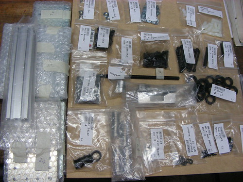
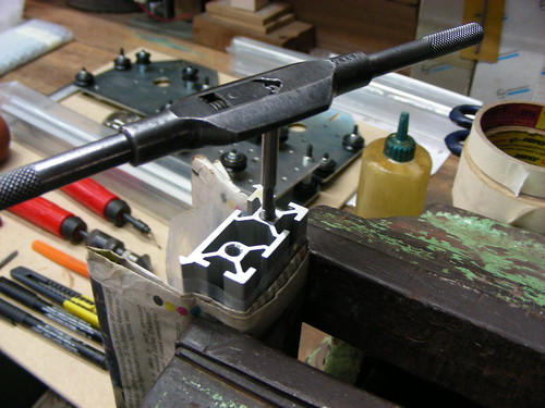
Well, I’ve had some time to start putting this kit together and it hasn’t been without a few frustrations…The body is laser cut MDF and the instructional videos (on youtube) are good and reasonably clear. For the most part, construction has been without major hiccups. It pays to put things together without the glue first to check alignment/fit etc then go back with the adhesive. Gluing the acrylic drive parts together took an alarming amount of superglue to actually get it to stick…The only significant issue i’ve encountered is that the steel rod guides can prove tight against the guide holes in the MDF, especially I’ve found for the Z-axis tool holder..even though the rods were inserted into the tool holder and ends whilst everything was glued, they still managed to setup a tiny bit out of line….several minutes of manually sliding it up and down has loosened it up a lot, but until I fire up the servo then I won’t know if it’s sufficient to prevent binding and hence vertical accuracy…Also the cuts on the threaded rod have proved poor so a little dressing with some small files is necessary before you can get a good thread for the locknut etc…
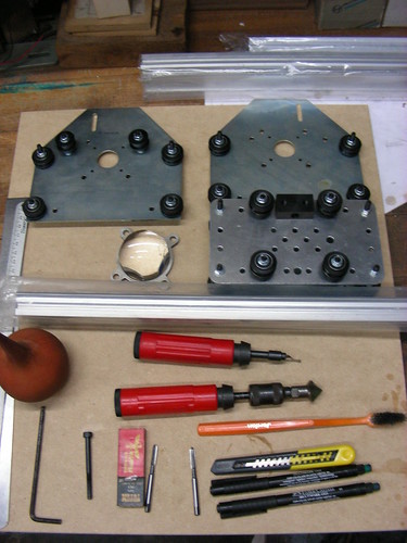
The main body frame was pretty straightforward and the movable bed is nice and ‘loose’ on it’s guides so shouldn’t prove a problem once in motion (Due to a minor ‘repair’ to the Z axis assembly, I started putting the other parts together out of order…the horror!).
You’ll note from the picture that it’s all controlled from an Arduino compatible driver board with a custom power control header for the CNC. At the front you can also see one of the servos which is attached to the threaded rod via an acrylic toothed gear and ‘socket’…we’ll see how well that holds up after some use. The degree of rod rotation (and hence board movement) is provided by a magnetic sensor at the end of the threaded rod (see picture below, there’s a magnet glued to end of the locknut)…
So far, I’m really enjoying putting this together, and there isn’t much left to finish it….then the fun starts as I try and figure out how to drive it from my Mac….The creators, Tom and Bar have come up with a really neat piece of open source kit!
The rest of the WyoLum crew get to have fun with laser cutters and 3D printers to build cool and interesting Open Source goodies for everyone. I figured I needed to get in on some construction action too, so I recently purchased a MakeSmith DIY CNC machine (www.makesmithtech.com) from their recently completed Kickstarter Campaign (I love Kickstarter…;-). It’s a very low cost entry into a small scale CNC set up (work area approx 9 inch square) for hobbies etc. and I couldn’t resist the idea of trying it out. Over the next few months I thought it would be interesting to post some updates to the blog detailing how I get on with putting it together and what I end up using it for..
When my WyoLum buddy in Boston, Kevin Osborn, built his “CNC AlaMode“, I just had to make one for myself too. Here’s how my build progressed.
I ordered the Mechanical Kit from Inventables with Dual Y-Axis motor upgrade– without any motors or electronics. For good measure, I also added in two lengths of MakerSlide, hoping to extend the axes at a later date. Being on the other side of the globe has its disadvantages, and it took almost two months after ordering the kit before I could lay my hands on it in April.
There were a few small bits and pieces missing, but nothing that I couldn’t replace from my local collection of hardware.
The mechanical assembly seemed straightforward. But first order of business was tapping all the MakerSlides with a 5mm tap. The full kits come with the slides already tapped, but the Mechanical only kits need to be tapped. This is not something that can be rushed, even though it was a hefty 5mm tap in an open-ended hole – one slip of concentration, and it is highly likely you’ll end up snapping a tap inside the hole.
Aluminum is a pretty “sticky” material, so make sure you lubricate the taps with cutting fluid while tapping. In between tapping the holes – so I wouldn’t get bored and snap a bit – I simultaneously went about assembling some of the other parts.
I did the initial assembly, but could not proceed further until I could manage to buy the stepper motors locally – which were out of stock.
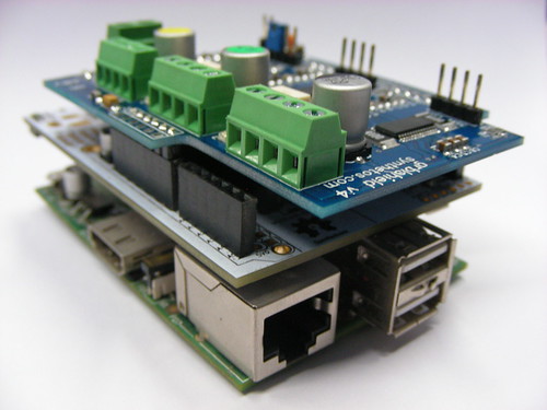
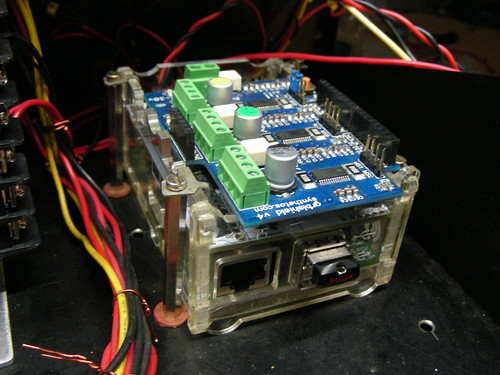
Meanwhile, I moved my attention to assembling the electronics. The computer for the ShapeOko would be a Raspberry-Pi, the microcontroller would be our very own AlaMode – an Arduino clone board, and the GRBLShield from Synthetos would drive the Motors.
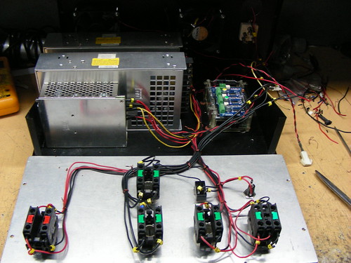
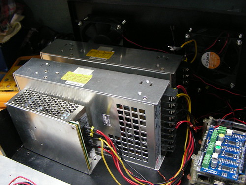
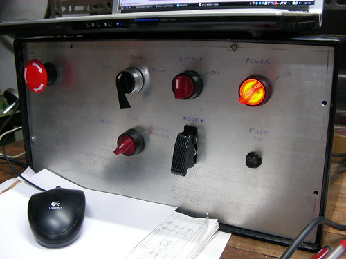
My plan was to put together a control box to house all the electronics. Here’s the full BoM :
Power socket outlet, 230V, 6A (to help power a laptop)
Power socket inlet, 230V, 6A
Once the motors arrived, I was able to complete the rest of the build quickly. One of the changes I made was to move the Y-axis drive pulleys on the outside. I had to move the Y-axis motors further away from the mounting brackets by about 20mm to accommodate the change. This extended the X-axis range by almost 40mm.
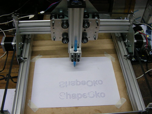
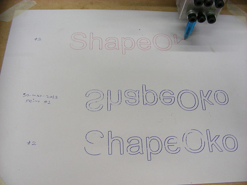
To do the initial “pen writing” trials, I made an aluminum block to allow mounting various types. My very first trial of the “ShapeOko” hello world was a mirror image. Turned out the dual Y-axis motors were running in reverse. I flipped a coil connection on both the motors, and the second trial was correct. I made a few more trials, using different pens, and printing some geometric patterns to check for any obvious errors in the right angles, circles and dimensions.
Raspberry-Pi Setup
I’m not much of a software guy, so I mostly followed the nice set of instructions on the Adafruit Learning System – to install the OS and utilities on the SD Card. It’s important to set up SSH and also remote control using VNC or similar. This allows you to log in to the Raspberry-pi from a remote computer.
Next step would be to set up the AlaMode on the Raspberry-Pi. Detailed instructions are available at this link : AlaMode User Guide – http://goo.gl/DtQy3
Once Alamode setup is complete, it’s time to flash “GRBL” on the AlaMode. I downloaded the HEX file for GRBL Version v0.8c – http://bit.ly/SSdCJE – and flashed it on the AlaMode using XLoader. My Linux-Fu was not strong enough to figure out how to flash the HEX code directly from the Raspberry-Pi to the AlaMode.
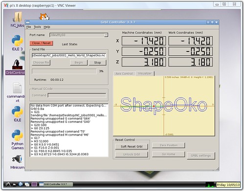
The final piece in the software chain was a means of sending a G-code file from the Raspberry-Pi to the ShapeOko. Initially, I tried “Universal G-Code Sender (https://github.com/winder/Universal-G-Code-Sender)”, but that runs on Java.
Unfortunately, running UGCS slowed down my Raspberry-Pi to a crawl. The reason, it seems was that the Adafruit Occidentalis can only handle soft-float operations. The regular Raspbian OS can handle hard-float operation, and thus runs Java code more efficiently / faster. While trying to improve the situation, my luck ran out, and I ended up messing up the OS. Took me a fair bit of trial and error (and lots of hair-pulling) to get the Ras-Pi running correctly again.
At which point I decided it was just not worth the effort to continue using Java on the Raspberry-Pi, and I looked around for better options. Luckily, I found an awesome G-Code sender specifically written for GRBL, called GRBLController, by Zapmaker. There were some initial issues, like not being able to set up the Alamode port (TTYS0), etc. But a couple of exchanges with the author, and he quickly sorted it all out. We sent an AlaMode to Zapmaker for him to test it out – you can read his blog report on the Alamode.
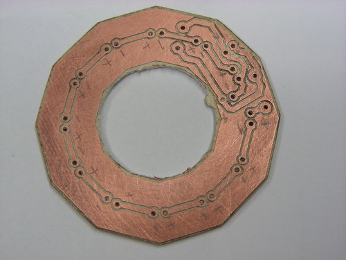
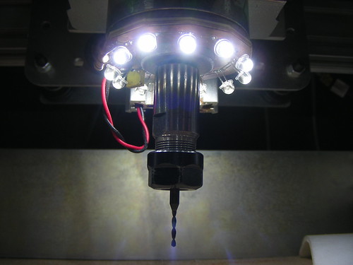
One of the first jobs I cut on the ShapeOko was a circular ring illuminator PCB which uses 12 LED’s to light up the cutting area under the spindle.
The bad news is that once again we are learning the hard way. I burned out our laser tube when water flow stopped unexpectedly (power strip?).
The good news is that we are now back in action. Here is how we did it in case there are any other slow learners out there.
We tapped into the auto shutoff circuit that shuts off power to the laser when the door is open. First we found this calibrated flow meter from SparkFun, then discovered this beauty from AdaFruit for only $9.99. We went with the AdaFruit, of course.
Carduino is a prototype of a project meant to be a automobile battery monitor that can shut off a peripheral when the battery voltage starts to drop. It was a simple matter to re-purpose the Carduino for this application.
The simple sensor has three leads: ground, 5V, and data. The data line toggles between low and high when water (or air) is flowing and is steady (high or low) when flow stops. The flow meter sample code provided by AdaFruit, gave us a jump start on the development. The protection circuit code is simple, if the delay between low and high toggles on the flow meter is longer than expected, shut off the solid state relay.
I had to channel my inner Anool to figure out how to wire the unit and could not have done it without a healthy portion of Bald Wisdom. It took a day. Here is the result. If you remove the side panel it is much easier.


cYvbwzg~~60_12.JPG)


 The fluid circuit was a challenge of fittings and space. I put the flow meter outside of the laser, but needed a right angle adapter to save space inside the laser. I had to cut a spacer to mount the assembly (see in photo).