
How to build a Desktop Word Clock (in a morning)
Reply

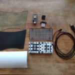
Cost: $100, Time: 2-4 Hours, Difficulty: Easy, Tools: Laser Cutter, 3D printer
Thanks to the modern maker tool suite, it is getting easier and easier to make topnotch builds very quickly. In the process of revamping ClockTHREEjr, we decided to prototype and test the matrix driving circuitry. A few short years ago (in the ClockTHREEjr era) addressable LEDs were not a thing yet. A large array needed to be displayed one column (or row) at a time before moving to the next column (or row). This makes the circuit and programming logic very complex. Smart addressable LEDs (like the APA102), with a microchip in each piecepart, make all of that complexity obsolete. With only 2 pins from a microcontroller, these pixels can be commanded to set and hold any 24-bit color as long as power is maintained. This frees up the processor to do other things, like poll user interfaces and read subreddits.
So the task is to redesign the ClockTHREEjr board using these modern smart LEDs. ClockTHREEjr (C3jr) has 8 rows and 16 columns of dumb LEDs, which can upgraded to smart pixels using 2 ULTiM8x8 (no solder) LED panels. What was originally just a proof of concept turned out to be so cool we decided to show it off and make the design public.
Once you have purchased the Bill of Materials (BoM), you can make this clock in a morning. Once you get your 3D printer started on the baffle (.5-3 hours depending on printer and settings), you can move over to your laser cutter to make the front and back of the clock (1 hour). Give yourself 30 minutes for final assembly and 30 minutes to program, even though neither takes that much time. That means you can make this project in 4 hours with plenty of margin. This project is a slam dunk.
Steps:
1. Print baffle
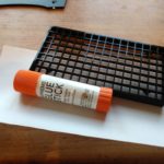
Since the baffle is not really visible in the assembled clock, it can be printed very quickly with large layer heights. Kevin Osborn was able to get the print time down to 25 minutes using a 1mm nozzle With the .4mm nozzle you can go up to .2mm layers. The rule of thumb is to make the layer height no more than 1/2 nozzle width. You can go higher, but this tends to get layer separation (theoretically you could do 1x nozzle width layers).

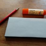
Glue the velum to the font of the baffle and trim away excess velum.


2. Lasercut faceplate and backplate
The faceplate is etched on the backside. The black letters are to be etched and the red lines are cut. Take your time here. You may need to slow the etching speed down or make more than one pass to remove all of the opaque material. There are several choices on the material. Black is by far the most popular but Inventables (see bill of materials) offers several color choices. The mirrored acrylic also works well. For a super glossy finish, use spray-painted acrylic with at least four coats of paint, the last coat being in black. Let dry completely between layers.

3. Program Feather Huzzah
Pre-requests: Install Arduino, Feather Huzzah dev env, adafruit IO account.
TLDR;
- Download the code from GitHub.
- Set sketchbook folder: KlokTHREEjr->arduino
- Create libraries/credentials/credentials.h
- Open arduino/DesKlok_IO/Desklok_IO.ino
- Board: Feather Huzzah
- Select port
- Upload
Download the code from github. You can either download the zip file or clone the repository. The stable code for this clock is stored in DesKlok_IO. The _IO in the name refers to the fact that we are using the Adafruit_IO library for controlling the clock. We will configure our IO controls after we upload the program to the Feather Huzzah.
Every WyoLum repository comes complete with all of the libraries you need installed in the “arduino/libraries” directory. Point your arduino->preferences->sketchbook directory to your downloaded KlokTHREEjr/arduino/ (On my system it’s “/Users/justin/code/KlokTHREEjr/arduino”).
Next we need to put wifi and adafruit.io credentials into a file called credentials.h. Open libraries/credentials/README and fill out your ssid, password and IO credentials.
#ifndef __CREDENTIALS_H
#define __CREDENTIALS_H
// Create a file called "credentials.h" that has ssid and pass as shown.
// This file should not be added to your public repository

char ssid[] = "YOUR_WIFI_SSID"; // your network SSID (name)
char pass[] = "YOUR_SSID_PASS"; // your network password
char* password = pass;

/************************* Adafruit.io Setup***************************/
#define IO_SERVER "io.adafruit.com"
#define IO_SERVERPORT 8883
#define IO_USERNAME "YOUR_IO_USERNAME"
#define IO_KEY "___YOUR_IO_KEY______" //copy paste AIO key

#endif
Finally restart Arduino. If the path is set correctly, you will see a few Klok sample programs in the File->Sketchbook menu. Open “DesKlok” from File->Skechbook->DesKlok. Select the “Feather Huzzah” board from the Tools->Board menu. Plug in your Feather Huzzah into an available USB port and select that port from the Tools->port menu in Arduino. Finally upload the code.
Adafruit.io setup
IO allows us to leave off the tedious physical interface and go with a purely virtual interface. To control the DesKlok, you will need to set up Adafruit.io. You will need to create three feeds on io.adafruit: klok_brightness (0 to 50), klok_display_idx (0,1,2), and Timezone1 (-720 to 720), klok_brightness. 
After you create the feeds, add dashboard to hold them. I used three slider-bars with the above limits.

4. Assemble
Make sure you test the electronics before you assemble the clock. Every time I build the clock without testing, I realize I forgot to solder the power jumper.
- Prepare bus
- Solder header and power jumper
- Test
- Final assembly

1. Prepare bus
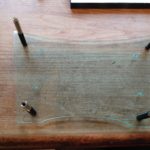
The bus can hold one, two or three ultim8x8s. Since we are using only two UlTiM8x8s, we need to remove some tabs from the bus as shown.


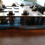
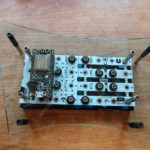
2. Solder headers and power jumper
Solder the female headers onto the bus board and the male headers to the Feather Huzzah.

Solder the included small switch to the bus or solder the center pad of the power jumper to the USB side.
 3. Test
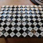
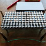
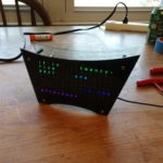
Plug the Feather Huzzah programed earlier into the bus. Start arduino and open the serial monitor. If all goes well (connect to wifi, and Adafruit IO) seconds will start ticking off.  Once you see the time in the serial monitor, your LED panel should be lit (shown below with baffles and velum).

4. Final assembly.
What can go wrong?
- Forget to solder jumper switch
- Light leakage.– mask holes in ULTiM8x8
- Wrong ULTiM8x8 orientation (double check 5V and ground rails)
Use thin (1.66mm) m3 nuts to attach low profile screws to each of two ULTiM8x8 boards. Mask the holes around the edge to prevent light leakage. 
Attach bus board, paying close attention that the 5V and ground rails align with the LED panels. Use 12 M3 nuts in the middle and 4 standoffs (20mm) in the corners. 
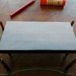
Attach the faceplate and backplates and you are done. The space between the faceplate and backplate is exactly 30mm. This can be filled a number of ways: 30mm standoff (preferred), 20mm standoff + 10mm spacer shown below (need longer M3 screws), 20mm and 10mm standoff (10mm standoffs come with ULTiM8x8).


On Willful Ignorance [or Age of Unreason]
[We take a departure from open hardware to discuss a dangerous trend in society]
I’m confused. How in the world did we get here? The war on science, reason, and logic has not seen this much success since the dark ages. Four in ten Americans reject evolution and many politicians deny climate change. The relentless fusillade on expertise has taken its toll and it is now open season on observation itself. Now we are told the truth doesn’t even matter.
oh… and by the way…. the Earth is flat (like your head). I know this goes against what you’ve been taught, but let’s dig a little deeper and suppress the initial reaction to reject the claim immediately. We can approach this scientifically and make observations that will either support or reject the claim.
In case you missed it, the Flat Earth Society suggests that the Earth is a flat disk with the North pole as its center and an ice wall near Antarctica preventing us from falling off. According to this theory, the sun is about 35 miles across and is suspended 3000 miles above the disk, completing one revolution per day around a circle centered 3000 miles above the North Pole. The seasons are caused by the changing radius of the circular path of the sun.
The image below shows in grey, the path the sun makes over the course of a year. Black diamond shows my point of observation outside Washington D.C.

We now have a scientific test we can apply to the Flat Earth conjecture. I’ve computed the elevation angle of the sun from my vantage point over the course of a year. Elevation angle is the angle of an object made by the horizon, the observer, and the object in the vertical plane. Below, the elevation angle is plotted vs azimuth.

They used to say “the sun never sets on the British Empire” well according to the Flat Earth society, the sun never sets on D.C. either! According to this model, the sun should NEVER go beneath the horizon. This contradicts the fact that we can observe the sun elevation angle reaching zero (when the sun sets). In fact, I should never witness the sun dip below 10 degrees elevation. Indeed there is no place on earth where the sun sets according to the Flat Earth Society. Can you please make an observation for me? If you’ve seen a sunset in your life, can you please state the time and location in the comments? Better yet, please post any photographic proof of your observation! Its citizen science in action.
A cult is an organization that asks you to reject your own observations and adhere to another explanation on faith. The Flat Earth Society is only one example. Crowd size is anorther. Denying Russian collusion is another. The question is why? and why now? As with any cult, there is power in deception. After the truth is cast out, a cult leader can fill the void with whatever he wants.
Science, not indignation, is the cure for ignorance: hypothesis, observe, conclude.
Lada to the rescue!!
Something else I’ve been working on for a while, in collaboration with another far more talented hobbyist (Grahame Marsh – www.sgitheach.org.uk) are Open Source CRT clocks and a CRT Tester. When confronted with the job of making a nice case for the CRT Tester, it occurred to me to use the wonderful Lada idea from Justin (https://wyolum.com/lada-a-custom-project-box-system/). Grahame, took the idea further and tweaked the Lada to integrate PCB holding and case construction in one piece! Hence the following gadget became a reality…

For more details of the Lada modifications or if you’re interested in an Open Source CRT tester, or even a Scope Clock then check out Grahame’s website or feel free to contact me for more information!
Cheers,
Nick
C3Jr 3D Printed Stand
It’s been a while….
Having played with 3D printers for a bit now, I thought it would be a good idea to elevate my C3Jr clock a little and make a stand for it. I recently put together a Prusa i3 MK2 printer from a kit, and it’s Open Source at its best! To break it in, I used it to make the stand! This would help with not only keeping the clock more secure (if it’s a desktop clock) but also add a little flair to the C3Jr. It’s nothing too fancy, but I think it turned out OK. The print was a 50% honeycomb infill to give it some strength and the STL file will be available on our GitHub in the usual place. Enjoy! Any questions, then shoot us an email.

