Building A Guitar Tuner With The New Ultim8x8 LED Panel

With the introduction of the Ultim8x8 boards came a desire to build something with them, and after bouncing idea after idea off of Mr. Shaw, we finally decided to build a guitar tuner. However, while one may have just resolved to use a simple vibration sensor in order to get the readings from the guitar, we decided to take the software up a notch, and now I am in the process of coding my very first Fourier Transform.

Essentially, the idea of this guitar tuner is that the player will play a note, which is then picked up by the microphone. A Fourier Transform is run on the note (the code will take the frequency of the code and round it to the nearest frequency, for instance, if I want to play an A440, but my guitar is tuned to play an A450, the program will assume that the player is trying to play an A440, and will accordingly notify the player), and then the note is displayed on the LED Panel, only its color will be an indicator that the note is either exactly tuned or it is a little off.

The process of building this guitar tuner has not been an easy one, but it certainly has been nothing if not an educational and overall exciting experience. Through Mr. Shaw, I was able to receive 3 microphones, as well as capital for the necessary parts for this project, which included a set of calipers, an Adafruit M0 Basic Proto Feather Board, a 2000 mAh LiPoly battery, a slide switch, some extra wire, and a delightfully colorful pack of heat shrink tubing. Below is a list of the steps I have taken so far in building the tuner:

  1. I first tried designing a 3d printed mount for the LED panel in TinkerCAD. However, the design I made proved to be too small for the panel to fit. Plus, I hadn’t thought about how the placement of the panel would affect the sound made by the guitar. Since this was a problem that I could easily fix, I decided to move on to the more challenging part of this project, which was the software.
  2. However, in order to test the software, I needed to set up the proper hardware. I soldered one of the Ramsey Electronics Microphones into the prototyping area of the Feather Board in order to test its effectiveness in picking up sound.
    1. I pulled some sample code from the Adafruit website, who uses the same microphone in their microphone breakout boards, and tested to see if I was getting a reading out of the device. Sure enough, the microphone was wired correctly and reading the beautiful sound of my voice.
  3. After a fruitful meeting with Mr. Shaw, who kindly explained to my perplexed self the art of the Fourier Transform, I started writing the software for the microphone.
    1. The first draft of my code was marginally successful, meaning that it compiled and that was about it. After a few suggestions from Mr. Shaw, I was able to fix most of my errors, and am still today working on tweaking and improving the code.
  4. My next step in the hardware side of this project was to solder the DATA, CLOCK, GROUND, and POWER pins from the Ultim8x8 board to the Feather so as to test it.
    1. Similar to how I tested the microphone, I downloaded the Adafruit DOTSTAR library and ran one of the sample programs on the board. Sure enough, it lit up like a Christmas tree!

Thus I have relayed upon to you, the reader, my progress so far. My next steps in the project include designing a better mount for the panel, fixing my software (which mainly involves figuring out how to include the complex exponential (e^2 pi i f t ) into my code), and ultimately integrating the software with the microphone and the software with the panel together. After all that, I will hopefully have a badass guitar tuner in my hands.

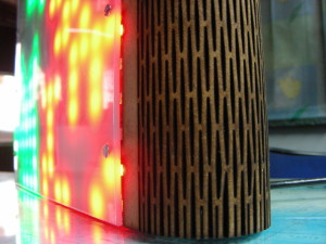
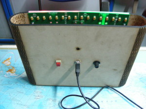
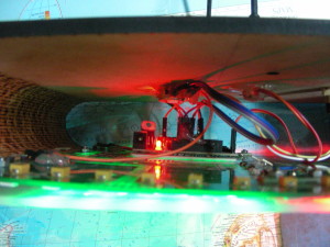
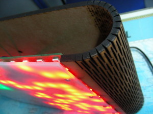
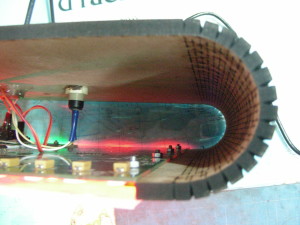
Below is a photo of the tuner so far.

guitartuner

Below is a photo of the microphones I received. I am using the one on the left for this project

microphones

Finally, below is a photo of my first take at the 3d printed mount.

led_panel_first_try

Uploading the New and Improved ClockTHREE Jr. Code

Hello! My last blog was about updating the ClockTHREE Jr. software, however, today I will be writing about the process of uploading the code all the way from the Arduino IDE to the master GitHub repository. Once I got the hang of it, the process was as easy as printing “Hello World” with Python.

  1. First, I downloaded Git on my Ubuntu Linux computer using the command “sudo apt get update” and then “sudo apt-get install git.” However, you can also just install it from the URL listed here: https://git-scm.com/downloads
  2. The, I logged into my own GitHub account and opened up the Wyloum repository. From there, I clicked the ClockTHREE Jr. tab.
  3. Once there, I forked the repository by pressing the (Well what do you know?) “Fork” button in the top right corner. This created a branch of the master Wyolum ClockTHREEJr repository in my own account. I did this so I can freely modify the code without affecting the master repository.

Screenshot from 2016-07-24 15-59-47

4. After clicking the Fork button, I went back to my personal account and I had the forked repository as rohanius/ClockTHREEjr. Next I cloned this repository to my hard drive. I did this by copying the git link by pressing the green button labeled “Clone or Download” (Make sure that when you push the button, the words “Clone with HTTPS” appear, not “Clone with SSH”).

Screenshot from 2016-07-24 16-37-52

5. I then opened a terminal and made sure that it was currently pointing to my “projects” folder (make sure next to the original line it says /projects). After that, type in “git clone https://github.com/rohanius/ClockTHREEjr.git”. This cloned the repository to my hard drive and created a folder in my “projects” folder and named it the same name as the repository – ClockTHREEjr

Screenshot from 2016-07-24 16-08-31

6. I was then able to edit the code as I pleased in my local repository.

7. After accordingly editing the code (which I explained in my previous blog), After compiling and testing that my code changes worked, I opened the terminal once again and changed the current directory to be /home/rohan/projects/ClockTHREEjr

8. In that directory, I typed “git commit -a -m “Updated code for Arduino 1.6.9”. This command committed all my local changes to the local git repository that I had cloned.

Screenshot from 2016-07-24 16-17-42

“-a” means “all the files in that directory that have been modified” and “-m” just allowed me to type a small message once I committed the code.

9. After committing the code, I simply pushed it to my GitHub repository using the command “git push”

Screenshot from 2016-07-24 16-19-54

10. Finally, I went back to my GitHub repository (rohanius/ClockTHREEJr.) and clicked the pull request tab. From there, I made a new pull request for the original owner of the ClockTHREE Jr. repository. Mr. Shaw was then able to pull all my changed and merge them to the master ClockTHREE Jr. repository.

Screenshot from 2016-07-24 16-23-37

Updating the ClockTHREE Jr. Software

One of my first tasks here at Wyolum was updating the old ClockTHREE Jr. software for Arduino 1.6.9, the newest version. I focused specifically on updating the file specified in the original tutorial for reprogramming the ClockTHREE Jr., ClockTHREE_04.ino. At first, when I tried compiling the sketch, the number of error messages that popped up frightened me. It was just a sea of blaring orange text, informing me on the multitude of errors spanning a variety of different documents. The task seemed to be very daunting, and I did not know if I would be able to complete this task. However, after I had gotten over my initial shock, i decided to be brave and actually read the error messages, rather than judge the difficulty of the task by their quantity. This act turned out to be immensely helpful, as after my analysis, I discovered that there were only 6 documents that needed to be changed, as opposed to my crazy original assumption of 20 or 25. Furthermore, there seemed to be one term that resonated throughout the error messages: “const.” With these 2 helpful facts in mind, I got to work. Below is a detailed analysis of what I did to the 6 documents:

  1. In the original file itself, ClockTHREE_04.ino, I included the english_v3.h file, uncommented the line that let the ClockTHREE Jr. account for Daylights Savings Time, and most importantly, changed “prog” in the line “PROGREM prog_uint32_t DST[] = {“ to a “const.”
  2. In the next document I changed, english_v3.h, I simply added a const after the “uint8/32_t” in the lines with WORDS[] PROGMEM, DISPLAYS[] PROGMEM, MINUTE_LEDS[] PROGMEM, and MINUTES_HACKS[] PROGMEM.
  3. The next file I had to change took me away from the ClockTHREE Jr. file and into the CHRONOGRAM2 file, where I had to update the english2_v1.h file. In this file, I changed “prog_char” to “const_char” in the lines with HOUR_WORDS[], HOUR_SEQ[], MINUTE_WORDS[], and MINUTE_SEQ[].
  4. In the files font.cpp and mem_font.cpp, I respectively changed “PROGMEM static char prog_char font8x8[] = {” to “PROGREM static const char font8x8[] = {“ and “static prog_char font8x7[] PROGMEM = {“ to “static const char font8x7[] PROGMEM = {.“
  5. In the final document I changed, DateStrings.cpp, I added a “const” to:
      1. char monthShortNames_P[] PROGMEM = “ErrJanFebMarAprMayJunJulAugSepOctNovDec”;
      2. char dayStr0[] PROGMEM = “Err”;
      3. char dayStr1[] PROGMEM = “Sunday”;
      4. char dayStr2[] PROGMEM = “Monday”;
      5. char dayStr3[] PROGMEM = “Tuesday”;
      6. char dayStr4[] PROGMEM = “Wednesday”;
      7. char dayStr5[] PROGMEM = “Thursday”;
      8. char dayStr6[] PROGMEM = “Friday”;
      9. char dayStr7[] PROGMEM = “Saturday”;
      10. PGM_P dayNames_P[] PROGMEM = { dayStr0,dayStr1,dayStr2,dayStr3,dayStr4,dayStr5,dayStr6,dayStr7};
      11. char dayShortNames_P[] PROGMEM = “ErrSunMonTueWedThrFriSat”;
      12. char monthStr1[] PROGMEM = “January”;
      13. char monthStr2[] PROGMEM = “February”;
      14. char monthStr3[] PROGMEM = “March”;
      15. char monthStr4[] PROGMEM = “April”;
      16. char monthStr5[] PROGMEM = “May”;
      17. char monthStr6[] PROGMEM = “June”;
      18. char monthStr7[] PROGMEM = “July”;
      19. char monthStr8[] PROGMEM = “August”;
      20. char monthStr9[] PROGMEM = “September”;
      21. char monthStr10[] PROGMEM = “October”;
      22. char monthStr11[] PROGMEM = “November”;
      23. char monthStr12[] PROGMEM = “December”;
      24. PGM_P monthNames_P[] PROGMEM =

After saving all of my changes, I compiled the code in Arduino 1.6.9, and to my utter delight, it worked!

a TiM Moodlight

dscn1798_26318788455_oA couple of weeks ago, I noticed a pair of old, first version TiM boards lying around at my local maker space, Maker’s Asylum and decided to put them to use by building a MoodLight. We love crazy names at WyoLum, and TiM is “The Intelligent Matrix”. We even tried building a controller for it called TiNA but it didn’t work out 🙂

dscn1788_26252600171_oTiM (The intelligent Matrix) is an array of 8×16 individually addressable 5050-WS2811 RGB “smart” pixels.  It is essentially 8 rows of 16 LED’s but with a very flexible connection scheme that allows you to control the whole array (128 LEDs) with a single pin or up to 10 boards (1280 pixels) chained together using 8 input pins. TiM boards can be linked together to create larger matrices. Stacking can be done in the vertical and horizontal orientations, and the pitch between individual LEDs is maintained when boards are stacked. Here’s the TiM User Guide.

dscn1793_26226395382_oI had two boards on hand, which I joined together to form a 16×16 matrix of 256 LEDs. TiM boards need an external controller, and I used an Arduino Clone that I designed for use at the Maker’s Asylum called MAPone (Maker’s Asylum Project #1). MoodLights require some form of user interaction, and I decided to use one push button (digital input) and one potentiometer (analog input). The whole thing is powered by a 5V wall wart.

dscn1799_26292824886_oFor the software, I tried some code I found on the web, but none of it did what I wanted – change modes by pressing the button, and change colors using the potentiometer. I can’t code if my life depended on it, so I chucked the problem at my go-to guys – Justin and Kevin. Justin is quick, like the Energizer bunny, and threw back code at me on the rebound. But it required using four potentiometer’s to control the colors. Since the HW was already wired up, I waited to see Kevin came up with something different, which he did. Nice code which allowed different modes to be selected by a button press. The first mode is the standard Rainbow colors from Adafruit’s StrandTest. Then, there’s a color changing mode, Breathing LEDs, Connection Machine (which looks something like Conway’s Game of Life), and finally a scrolling Text mode. This is enough to start with, and I’m sure if anyone at the Asylum wants to hack and dig in to the code, there’s a lot for them to play around with.

dscn1805_26363162042_oI designed the enclosure in OpenOffice Draw. A laser cut piece of MDF that wraps around the TiM PCB using some “living hinge” bends. I tried some junked 3mm MDF first, but the material was kinda bad – some parts cut well, while other areas were left with a charred and burnt top layer, so I had to scrap that. Next, I tried 5mm MDF that way lying around, and while it cut well, it was a tad thicker than I preferred and the hinges were stiffer being designed for thinner 3mm MDF. Anyhow, it worked and I was keen on just finishing this off. I also cut an additional square piece of 2mm white polypropylene sheet for the front diffuser. Most of the electronics was stuck in place using generous globs of hot glue. I added some hand drawn graphics to wrap it off, and left it at the asylum. Let’s see how they mount it up.

Here’s a video walk through of the MoodLight.

EDIT : Here’s a better walk through of the code by Kevin Osborn

MoodLight for TiM (The Intelligent Matrix)

Introducing VeloKey, the keyboard for your bike.

2015-02-28_0810260

Let’s face it, indoor training kinda sucks.  But our friends at Zwift.com have made it suck a lot less.  Actually they made it kinda fun.  Zwift allows you to ride with real friends and cyber friends in a virtual world.  You interact with the environment with (besides your bike) a keyboard, a mouse and a phone app.  It is great as is, but we’ve come up with a more intuitive interface we call VeloKey.

IMG_20160301_190323938

VeloKey is a Bluetooth interface to Zwift that consists of two a 1.8 inch dis,play thumbwheels, and a power up button.

VeloKey’s main screen allows you to navigate the Zwift world, and control the camera angles with ease.

IMG_20160301_192023109

Double-click the right scrollwheel to kick into Etch-a-mouse mode: left thumbwheel controls left-right mouse motions and the right thumbwheel controls the up-down mouse movement.  Pressing either thumbwheel acts as a mouse button.  Press both button’s in succession to get a double click on the connected computer.

IMG_20160301_193057374 (1)

Double click the left scrollwheel to activate the keyboard mode complete with caps, lowercase, letters and numbers, and don’t forget backspace.

IMG_20160301_193111135 (1)

VeloKey make riding indoors even more fun!

IMG_20160225_192746874


VeloKey is an Open Hardware project.  Download source files here.