My brother is a Mechanical Engineer who loves his KTM Duke 200 bike. He asked me to build this circuit : http://sunbizhosting.co.uk/~spiral/blog/?p=227 for a ‘heartbeat’ lamp controller for the parking light. A Neutral Detect (ND) signal controls the lamp pulsing. When ND is HIGH, the Lamp is fully lit. When ND goes LOW, the lamp starts pulsing.
I’m not familiar with PIC microcontrollers, and didn’t want to dabble in “C” code. I’d be comfortable with an Arduino, but even the smallest ATMega seemed too big (and overkill) for this simple requirement. How about an ATTiny ? A bit of Googling, and I found this excellent resource for running the Arduino environment on the ATTiny : http://hlt.media.mit.edu/?p=1695
Time to churn out a circuit. I selected the ATTiny45 which has 6 I/O pins, with two of them being PWM, and three Analog. The schematic and board layout (in KiCad) can be found on the wyolum code repository at Google Code. The idea was to have a board that plugs in to the existing lamp socket. The board size is about the same as a T10 lamp. A new socket is wired to the p.u.l.s.e. board which then attaches to the lamp. A third wire from the p.u.l.s.e board goes to the Neutral Detect (ND) signal in the bike. This makes the installation clean and simple.
3D render of the p.u.l.s.e. board

3D render of the p.u.l.s.e. board
The 6 way header is ICSP for programming the ATTiny.
p.u.l.s.e boards

p.u.l.s.e. boards
Assembled p.u.l.s.e board

Assembled p.u.l.s.e board
Green wire is for ND signal. Red and Black go to a Lamp socket. The p.u.l.s.e board plugs in to the original lamp socket.
Now for the Important bits – getting Arduino to run on the ATTiny. These are the steps :
PHASE I – Get the ATTiny boards.txt files
1. Download ATtiny hardware description files for the Arduino environment from here : https://github.com/damellis/attiny/zipball/Arduino1
2. Create a sub-folder called “hardware” in the Arduino sketchbook folder (find its location from preferences dialog in Arduino IDE)
3. Copy attiny folder from inside the downloaded .zip to the hardware folder. You should end up with folder structure like Documents > Arduino > hardware > attiny that contains the file boards.txt and another folder called variants.
4. Restart the Arduino IDE.
5. You should see ATtiny entries in the TOOLS > BOARD menu.
PHASE II – Hook up the ATTiny to the Programmer (Arduino Duemilenove)
6. I used an Arduino Duemilenove board as the Programmer. There are other options (see the original post).
7. Plug the ATTiny in to a prototyping board, and link up wires between the Arduino and the ATTiny as follows :
ATTiny <-> Arduino

Pin 1, RESET <-> Digital Pin 10, SS

Pin 2, NC <-> x

Pin 3, NC <-> x

Pin 4, GND <-> GND

Pin 5, MOSI <-> Digital Pin 11, MOSI

Pin 6, MISO <-> Digital Pin 12, MISO

Pin 7, SCK <-> Digital Pin 13, SCK

Pin 8, VCC <-> 5V
8. Load ArduinoISP sketch in to the Arduino IDE. This sketch can be found under the examples menu.
9. For ARDUINO 1.0, find the line in the heartbeat() function which says “delay(40);” and change it to “delay(20).
10. Download this modified ArduinoISP sketch to the Arduino Duemilenove board.
11. Connect a 10uF, 16V electrolytic capacitor on the Arduino Board, between the RESET and GND pins. [+] of cap. goes to RESET and [-] of cap. goes to GND.
PHASE III – Change Fuses on ATtiny and burn Arduino Bootloader
12. ATtiny runs at 1MHz by default, out of the box. To make it compatible with Arduino IDE, it needs to run at 8MHz.
13. Select the 8MHz option for your selected ATtiny chip (“ATtiny45, internal 8MHz” in my case) from the TOOLS > BOARD Menu.
14. Select TOOLS > PROGRAMMER > Arduino as ISP
15. Select TOOLS > BURN BOOTLOADER
16. That’s it – done. You can now load Arduino sketches in to the ATtiny, using the same connections that you have already set up.
17. For the ATtiny45, the Port definitions are as follows :
ATtiny45 Pin No <-> Arduino Pin No

Pin 1, <-> PB5

Pin 2, <-> Pin 3, Analog Input 3 (PB3)

Pin 3, <-> Pin 2, Analog Input 2 (PB2)

Pin 4, <-> GND

Pin 5, <-> Pin 0, PWM (PB0)

Pin 6, <-> Pin 1, PWM (PB1)

Pin 7, <-> Pin 2, Analog Input 1 (PB2)

Pin 8, <-> VCC
For the other ATtiny chips, the table will be different. Check the ATtiny datasheet for details.
18. After Bootloader is burnt to the ATtiny, you can load the BLINK sketch to verify if it all works well. Change Pin 13 to Pin 0 before uploading the sketch, and you should get the blinking LED between PB 0 and GND of ATtiny (Pins 5 and 4)
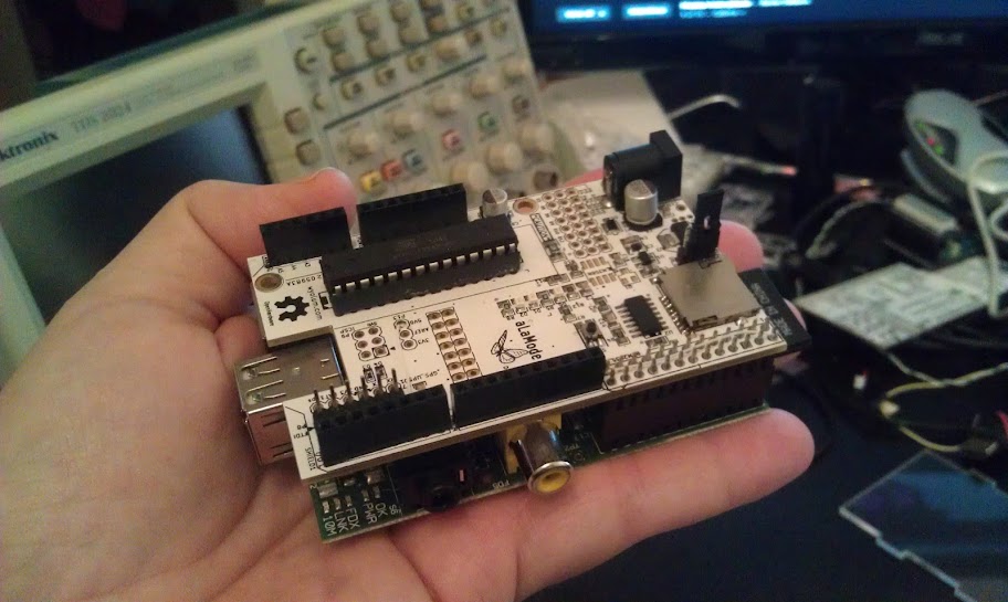
Connections between Duemilenove Board and p.u.l.s.e for burning bootloader and downloading sketches (note the 10uF capacitor between RESET and GND of Duemilenove)

Connections – Duemilenove to ATtiny
EDIT :
Video of p.u.l.s.e
Another video after installation in the Bike