ClockTHREEjr circuit validated

ClockTHREEjr is on its way to reality.  This week we’ve validated the matrix archetecture, finalized the schematic, designed the enclosure, and are nearly complete with the layout!

FlorinC is the project lead on this one.  Anool is doing a bang up job on the hardware design, I’ve been heading up the enclosure design.  Go Go WyoLum!


The First Cut… goes deeper in.


After a few tries Shyama and I got the router actually cutting a real part, of our own design!  Ok, granted it was a simple part, but its a start.  The part, a  ClockTHREE stand consists of two end pieces connected by a couple of dowels.  It was cut from 1/4 inch plywood.  I think it would be really nice out of 1″ hardwood and skip the dowels.  Have to see if Angus Hines has any suggestions.

Here is what we learned.  In MeshCam, you can define part supports that hold the part in place for the entire cut.  Because, as we discovered, the router does not work just as soon as it becomes free from the stock material!  It turns out this option is only available from STL generated files.  Our first runs  from bitmaps were doomed from the start.

We also were seeing some strange cuts until we realized that a “ballmill” bit had been selected rather than an “endmill”.  Fixing that also decreased the total cut time.

Here is the tool chain:

  • Python to generate OpenScad code
  • OpenScad generates STL
  • MeshCam generates GCode (ngc)
  • EMC2 executes GCode on Router

It works, but may not be the most efficient.

We have a long way to go, but we are making progress!

MORE pics

ClockTHREE Jr w/ FlorinC!

FlorinC has come up with ClockTHREE Jr! This is a smaller PCB with 112 individually addressable mono LEDs.  Anool and I have agreed to team up with him.  We still need to decide the final architecture.  I think it would be super easy to base it off of ClockTHREE with only one rtcBOB.  Florin has been working with another design.

Should be great fun.

UPDATE:

Florin decided to to go with the ClockTHREE design.  Anool pointed out that rowBOB will actually support 16 rows of LEDs and we only need 8.  He also pointed out the perfect replacement part.  Should save money and be easier to build.  Also, this will be our first board with the new OSHW logo!  

Probotix Fireball Comet Quickstart Guide

This post is geared to getting your Probotix Fireball Comet up and running as easily as possible.

Before you begin, take some time to make sure your Comet is complete and you are ready to go.  Consider this checklist the minimal requirements.


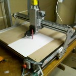
Included in the Fireball Comet complete kit

– Fireball Comet CNC router

– Computer

– Display

– Mouse

– Keyboard

– Joystick

– Probotix ProboStep stepper motor controller

– Network connectivity (strongly recommended). Contact probotix for the root password to your system. Change the password immediately!

You Supply

– 7 Electrical outlets (power strip)

– 36″x48″ sturdy table for Router

– Computer table or stand

Setup:

– Set up the compter, display, keyboard and mouse.parallel port – Plug joystick into computer. As configured EMC2 will not run without the joystick plugged in.

– Connect the ProboStep parallel connector to the central parallel port. There are three parallel ports on the computer. As configured, only this port will work.

– Position the comet so that the cables reach the ProboStep controller.

– Connect the X, Y, Z and A cables as labeled. Connect the final round plug (unlabeled) in to the last remaining space.

– Connect the e-stop cable. This looks like a small headphone jack.

– Connect spindle power cord into ProboStep

– Connect the four power plugs from the ProboStep into a power strip.


Continue reading

CNC router: Its alive!


We were amazed by the hardware, but really disappointed but the utter and complete lack of any documentation!  It took us three sessions to get it working.  Nothing was wrong that a quickstart guide could not have remedied.   Maybe we should offer to write a guide for them.

Anyway it is very exciting to get this up and running.